



What is a slew drive? A slew drive is a compact unit that combines a slewing bearing, a gear set, a housing, and a motor interface. It rotates a load and carries axial, radial, and tilting forces in one package. In a solar tracker, it turns the array toward the sun and must also hold it still in wind.
Here is the sourcing risk. Many datasheets list a holding torque, but few say how that number was measured or what load case it covers. If you approve a dual axis solar tracker slew drive on a headline number alone, you may find the gap during the first storm. This article shows how to check the claim before you place an RFQ or approve a prototype.
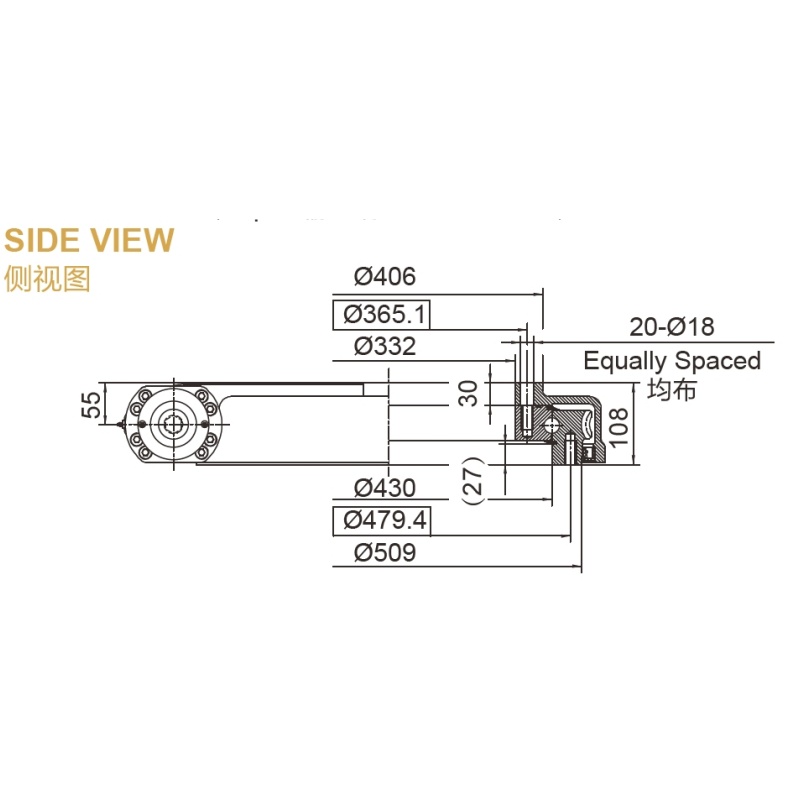
What a Holding Torque Number Actually Tells You
Holding torque is the torque a drive can resist at standstill without the output moving or the gear teeth failing. It is not the same as running torque, and it is not the same as the tilting moment capacity of the bearing. A datasheet may quote any of them under the same name.
Ask which limit sets the published number. It could be tooth bending, tooth contact stress, worm lock, housing strength, or bolt capacity. The lowest limit governs, and the supplier should be able to say which one it is.
| Term on a datasheet | What it may mean | Question to ask |
|---|---|---|
| Static holding torque | Output torque held at rest before slip or damage | Is it a calculated value or a tested value? |
| Rated output torque | Torque for continuous or duty-cycle running | Does it apply at standstill in wind? |
| Self-locking | Worm gear resists back-driving | Is this verified under vibration and gusts? |
| Tilting moment capacity | Bearing limit under overturning load | Is it checked together with the torque load? |
A worm gear slew drive often gives self-locking at standstill. A spur gear design usually does not, so it relies on the motor brake or a gearbox stage. Which one fits depends on your stow strategy, and neither is a universal answer.
Load Inputs to Send Before You Compare Quotes
A supplier cannot confirm a rating without your load case. Send the inputs below with the RFQ. Without them, any quoted torque is only a catalog value.
- Array geometry: projected area, mass, and center of gravity relative to each axis.
- Wind-stow condition: design wind speed or pressure, stow angle, and direction of the worst gust.
- Center of pressure offset: the distance from the axis to where wind force acts. This sets the moment arm.
- Axis roles: which axis carries the azimuth (rotation) load and which carries the elevation (tilt) load.
- Other loads: snow, ice, seismic demands, and the dead load of the array.
- Environment: temperature range, dust, salt, and the protection and corrosion levels you need.
The example below uses illustrative numbers only. They are not product data.
| Step | Illustrative value | Result |
|---|---|---|
| Wind pressure at stow | 1,000 Pa | - |
| Projected area | 20 m² | Force = 20,000 N |
| Center of pressure offset | 0.4 m | Moment = 8,000 N·m |
| Gust factor | 1.25 | 10,000 N·m |
| Safety factor | 1.5 | 15,000 N·m required |
In this case, a drive with a 12,000 N·m static rating would fail the check. The headline number looked large, but the margin was not there. Use your own project standard for gust and safety factors.
Matching Holding-Torque Claims to Wind-Stow Loads, Safety Factors, and Test Evidence
This is the method I use when I review a supplier claim. In 30 years of mechanical design work, the same gap shows up often: the claim exists, but the link to a real load case does not. Work through each row and mark it as confirmed or open.
| Claim to check | Compare it with | Evidence to request | Red flag |
|---|---|---|---|
| Published holding torque | Your wind moment times gust and safety factors | Calculation sheet or test record with the failure mode named | Single number, no method |
| Self-locking | Back-driving torque from gusts and vibration | Test at stow angle, or a brake specification | "Self-locking" with no conditions |
| Bearing capacity | Combined axial, radial, and tilting moment | Load curve for the slewing bearing | Torque quoted, bearing limits omitted |
| Bolt and housing strength | Interface forces at peak load | Bolt grade, preload, and mounting flange details | No mounting data |
| Ingress and corrosion rating | Site climate and expected service life | Protection level and corrosion class stated for the exact model | Rating given for the product family only |
Five steps to close the gap
- Calculate your peak wind moment on each axis, using the inputs above.
- Multiply by your gust and safety factors to get the required rating.
- Ask the supplier which limit governs its published torque, and compare it with your required rating.
- Request the test or calculation record behind the number.
- Check bearing, bolts, and brake or lock in the same load case, not one at a time.
Limits apply. A wide safety factor does not replace testing, and a test on one size does not prove another size. If the model is a variant, ask whether the record covers that exact variant.
Request Your Custom Slew Drive or Bearing Spec
Tell us your load, speed, and environment — receive a tailored 100–5000 mm slewing drive or slewing bearing proposal with 3D drawings within 24 hours.
Test Setup and Report Fields to Request
A useful holding-torque test is simple. The drive is mounted as it will be in the field, the output is loaded through a lever arm or torque device, and displacement is recorded as load rises. Then the load is held, and the unit is inspected for tooth damage, slip, or permanent set.
Ask for a report with these fields:
- Model number, serial number, and gear ratio
- Mounting method, bolt grade, and bolt torque
- Applied load, hold time, and load direction
- Measured output rotation or backlash change under load
- Whether a brake or motor was engaged during the hold
- Post-test inspection result and any observed damage
- Test date, equipment, and calibration status
Check the hold time. A momentary peak is different from a load held through a storm. Also check lubricant and temperature, because grease behavior at cold or hot extremes can change what the drive holds.
Common mistakes in torque verification
- Comparing catalog numbers only. Two vendors may define "holding" differently.
- Ignoring the moment arm. A small offset error changes the required torque a lot.
- Skipping the bearing check. A drive can hold torque and still fail in tilting moment.
- Using one axis for both. Azimuth and elevation loads are different.
- Accepting "self-locking" as a stow plan. Wind gusts and vibration need a defined check.
What We Can Support, and What Still Needs Agreement
Luoyang Slewring Bearing Co., Ltd. offers slew drive products, slewing bearings, and customized slew drive designs. The company has been active since 2012, with 6 production lines and an 8,000 m² facility. It holds ISO 9001:2015 certification and CE marking for the European market, and factory audit reports are available on request.
For torque verification, the relevant strengths are narrow and specific. Each slewing bearing passes CMM three-coordinate inspection and dynamic load testing, and the company reports a failure rate below the 0.5% industry standard. You can read more on the slew drive quality control page. Ask for the inspection records that apply to your order.
Solar experience is real but should be read carefully. SP-I 0229 spur gear slew drives went to South American solar projects in Brazil, Argentina, and Chile for single-axis trackers, and the customer reported energy yield gains of up to 40%. A US renewable energy equipment manufacturer ordered 50 units of SP-I 0841 for utility-scale solar trackers with IP65 protection for desert sites. These cases are single-axis or utility-scale tracker applications. They do not prove a dual-axis load case, so your dual-axis inputs still need a project-specific review. For related models, see the SP-I slew drive range.
| Term | Supplied condition | To agree with you |
|---|---|---|
| MOQ | 1 set standard, 5 sets customized; sample orders welcome | Sample scope and test criteria |
| Lead time | 3-day rapid prototyping, 9-day standard production cycle, technical proposal within 24 hours | Timeline for your specific design |
| Warranty | 2-year extended quality warranty; free replacement for confirmed manufacturing defects | Acceptance test and defect definition |
| Support | 48-hour technical response | Who owns the load-case calculation |
| Protection | Up to IP66; corrosion rating up to C4H | Rating for your exact model and site |
Lead times are standard figures, not a promise for every order. Customized torque ratings, gear types, or mounting changes may extend them. Agree on the acceptance test, the report format, and the responsibility for the load-case input before you sign off a prototype.
Information to Send With Your RFQ
To qualify a dual axis solar tracker slew drive quickly, send a short package. It lets an engineer check your requirement against a real design instead of guessing.
- Array area, mass, and center of gravity for each axis
- Design wind speed or pressure and stow angle
- Required safety factor and the standard you follow
- Preferred gear type, such as spur gear slew drive or worm gear
- Site temperature range and protection or corrosion needs
- Annual volume and whether you need samples first
If you are looking for a supplier for tracker slew drives, contact us to get the latest quotation. Include the load inputs above, and we will respond with a technical proposal and the documents you should expect for torque verification.
Request Your Custom Slew Drive or Bearing Spec
Tell us your load, speed, and environment — receive a tailored 100–5000 mm slewing drive or slewing bearing proposal with 3D drawings within 24 hours.
 WhatsApp

 +8613903880726