



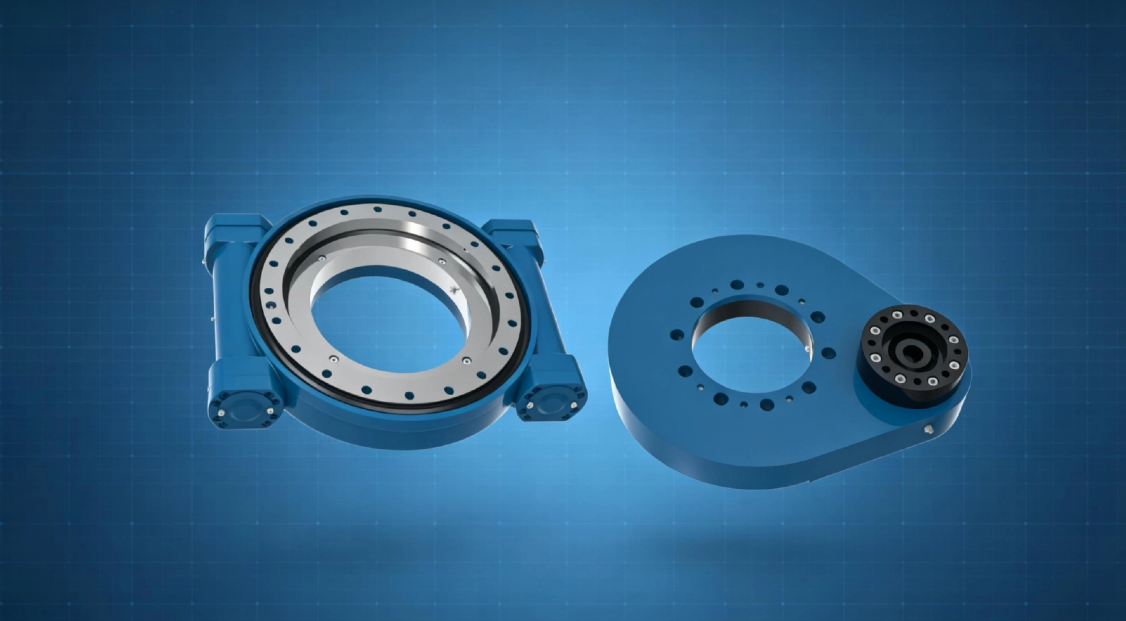
What is a slew drive? A slew drive is a compact rotary transmission that combines a slewing bearing, worm gear, housing, and drive input to rotate an attachment under load. On an excavator attachment, it commonly sits between the hydraulic motor and the rotating tool, such as a grapple, tilt rotator, crusher, cutter, or sorting attachment.
A slew drive for excavator attachment use can fail early even when its static load rating appears adequate. The usual cause is not steady rotation. It is hydraulic shock created by sudden stops, abrupt reversals, pressure spikes, or valve settings that allow the attachment’s stored energy to strike the worm gear and bearing.
For hydraulic attachment designers, the selection question is therefore broader than “How much torque does the motor produce?” The better question is, “What happens to the drive when the attachment stops, reverses, or hits an obstacle?” That answer should guide drive selection, hydraulic circuit design, and validation testing before final component approval.

Start with the actual load path instead of motor torque alone
The rotating attachment transfers force through several connected parts. Hydraulic motor torque enters the worm shaft, the worm transmits force to the worm wheel or geared ring, and the slewing bearing carries axial load, radial load, and overturning moment from the attachment. A shock event travels through the same path, but much faster and less evenly than normal operating torque.
Choose the drive based on the full load path when the attachment has an offset center of gravity, handles irregular material, or can contact the ground, a truck body, or a fixed structure. Motor torque alone may be a useful starting point, but it does not show the bearing moment created by a heavy tool extending away from the rotation center. It is not enough for attachment designs with impact exposure.
For example, a rotating grapple may carry a log with the load positioned away from the drive center. Even if the hydraulic motor operates at a controlled pressure during normal rotation, a sudden stop can turn that offset mass into a large overturning force. The bearing and mounting bolts must resist that event while the worm gear absorbs the torque reversal.
| Load or event | Primary component affected | What designers should evaluate | When it matters most |
|---|---|---|---|
| Continuous rotation torque | Hydraulic motor and worm gear | Normal running torque, duty cycle, and expected speed | Steady sorting, positioning, or low-impact rotation |
| Attachment weight | Slewing bearing and mounting structure | Axial load and center-of-gravity location | Heavy grapples, cutters, and long attachment frames |
| Offset working load | Bearing raceway and mounting interface | Radial load and overturning moment during rotation | Forestry, demolition, and material handling tools |
| Sudden stop or obstacle contact | Worm gear, worm shaft, bearing, and bolts | Shock torque path, valve response, and mechanical clearances | High-inertia tools and impact-prone duty cycles |
| Fast direction reversal | Worm tooth contact surfaces and hydraulic circuit | Backlash, reverse pressure, and deceleration control | Sorting attachments and repeated positioning cycles |
A standard Slew Drive can be suitable when the attachment load, mounting arrangement, and hydraulic circuit are known and controlled. When the attachment is new, unusually heavy, or exposed to repeated impact, designers should provide the supplier with the attachment mass, center-of-gravity position, motor information, working pressure, and operating sequence. Without those inputs, a torque-only selection can miss the governing failure mode.
How pressure spikes, abrupt reversals, and relief-valve settings transfer shock loads
Hydraulic shock begins when oil flow changes faster than the rotating system can respond. The hydraulic motor attempts to change speed or direction, while the attachment’s inertia attempts to keep moving. That mismatch produces a torque event that enters the worm shaft and is then transferred into the worm gear teeth, bearing raceways, housing, and mounting structure.
The three conditions below often interact. A relief valve can limit pressure, but it cannot remove all mechanical inertia. Likewise, a strong worm gear does not protect the attachment if the hydraulic circuit repeatedly creates sharp pressure transitions.
| Hydraulic condition | What happens in the circuit | Mechanical effect in the slew drive | Design response |
|---|---|---|---|
| Pressure spike | Pressure rises rapidly when flow is blocked or deceleration is too sudden. | Motor torque rises sharply and loads the worm tooth contact area. | Review relief protection, hose routing, valve response, and stop strategy. |
| Abrupt reversal | Motor flow changes direction while the attachment still rotates in the prior direction. | Worm tooth contact shifts quickly, creating impact across backlash and loading the bearing. | Use controlled deceleration before reversal when the cycle permits it. |
| Relief valve set too high | The circuit allows higher pressure before relief action begins. | Higher available motor torque can increase shock force through the drive. | Set protection according to the approved attachment and drive limits. |
| Relief valve response too slow | Pressure can rise before the relief function stabilizes the event. | A short-duration shock may reach gear and bearing components first. | Validate response under actual hose volume and duty conditions. |
| External tool impact | The attachment is forced to stop by material, ground contact, or structure contact. | Stored rotational energy drives reverse load through the bearing and worm gear. | Limit impact exposure through operating logic and mechanical stop design. |
Pressure spikes do not act on the worm gear in isolation
When pressure rises, the hydraulic motor produces more torque. That torque presses the worm against the worm wheel tooth surfaces, and the attachment resists rotation because of its inertia or external load. If the attachment is offset from the rotation center, the same event can also increase overturning moment on the bearing.
This is why a drive that appears acceptable during a bench rotation test may show damage during field work. Bench testing often has less attachment inertia, less hose volume, fewer obstruction events, and fewer harsh reversals. Field validation must reproduce the real tool mass, working posture, and hydraulic control behavior.
Abrupt reversal can turn backlash into impact
Backlash is a necessary operating clearance in a worm-drive system, but it becomes a shock path when direction changes suddenly. During reversal, the rotating attachment may continue moving while the motor begins driving the opposite direction. The clearance closes quickly, and the gear contact can receive an impact rather than a gradual transfer of torque.
Do not assume that reducing backlash alone solves reversal shock. Too little running clearance can create other problems, including heat, friction, and poor lubrication behavior. The better approach is to match gear clearance, attachment inertia, hydraulic deceleration, and reversal timing as one system.
Relief settings are a protection choice, not a motor-performance setting only
A relief valve setting influences the maximum pressure the motor can see under resistance. Because hydraulic motor torque is related to pressure, that setting also affects the torque available to load the worm gear. Raising the setting to improve breakout performance can increase the force transmitted during a stall or hard stop.
Use a higher setting only when the drive, bearing, attachment frame, fasteners, hoses, and motor have been checked for the same condition. It does not apply as a blanket solution for slow rotation or difficult material handling. If the attachment cannot safely absorb the added torque, higher pressure simply moves the risk into the drivetrain.
Request Your Custom Slew Drive or Bearing Spec
Tell us your load, speed, and environment — receive a tailored 100–5000 mm slewing drive or slewing bearing proposal with 3D drawings within 24 hours.
Choose the drive arrangement for shock exposure and attachment behavior
Drive configuration affects how an attachment responds to uneven loads and repeated reversals. A single-worm arrangement may fit controlled rotation tasks with predictable loading, while a dual-worm design can be considered where the attachment needs greater resistance to external torque and more stable positioning. The correct choice still depends on the actual load case and hydraulic control method.
For high-impact applications, the first selection step is not to choose the largest housing. It is to define the highest-risk event: a stalled grapple, a cutter hitting material, a loaded attachment reversing, or a tool striking a mechanical stop. Then assess whether the bearing, gear set, mounting bolts, and hydraulic protection all support that event.
- Single-worm drive: Suitable for applications with managed loads and controlled rotation. It may not be the preferred configuration when external torque and reverse loading are frequent.
- Double-worm drive: Consider it where attachment stability and resistance to external rotational force are major priorities. It still requires correct valve settings and a suitable mounting structure.
- Custom drive arrangement: Appropriate when the attachment geometry, hydraulic motor interface, corrosion exposure, or mounting pattern differs from standard products. It is not necessary for every attachment, but it can reduce integration risk for a new design.
Luoyang Slewring Bearing Co., Ltd. supplies standard and Customized Slew Drive solutions for equipment builders. Standard products can be ordered from one set, while customized products have a five-set minimum order quantity. Sample orders are welcome for testing and evaluation, which can help designers validate a new attachment before wider deployment.
For reference, a forestry equipment manufacturer in British Columbia ordered WED14-86-25BHR.5 double worm slew drives for grapple machines, with stated precision of no more than 0.13 degrees. That case supports the relevance of double-worm configurations in grapple equipment, but it does not establish a universal drive size or setting for every forestry attachment. Attachment mass, hydraulic circuit behavior, and working impact must still be reviewed separately.
Validate the hydraulic circuit before approving the mechanical design
The hydraulic circuit should be reviewed as part of the drivetrain, not as a separate package. A properly sized bearing and worm drive can still be exposed to damaging loads if the motor stops too abruptly, the valve shifts too aggressively, or relief protection does not match the attachment’s real operating condition.
Use the following procedure during prototype validation. It is especially useful for attachment designers who are moving from CAD calculations to machine testing and need to identify shock risk before field deployment.
- Document the rotating mass: Record attachment weight, payload range, center-of-gravity location, and the farthest working radius from the rotation center.
- Map operating events: List normal rotation, loaded rotation, deceleration, reversal, stall, material contact, transport position, and any mechanical stop condition.
- Confirm motor data: Identify displacement, expected flow, working pressure, and the direction-change command sequence used by the control valve.
- Review pressure protection: Check relief valve settings, crossover protection where used, and the expected valve response during blocked flow or sudden deceleration.
- Inspect the mounting interface: Evaluate bolt pattern, flatness, attachment frame stiffness, and whether deflection can distort the bearing support.
- Run controlled tests: Begin with low-risk motion, then test loaded rotation and reversals while monitoring for abnormal noise, heat, looseness, or pressure behavior.
- Reinspect after testing: Check fastener condition, gear engagement signs, lubricant condition, mounting surfaces, and any change in rotational feel.
Do not validate only at no-load speed. A no-load test may confirm that the motor turns the attachment, but it does not represent a loaded stop or reversal. The test should include the inertia, load position, and hydraulic sequence expected in the field.
Our facility can provide a technical proposal within 24 hours after receiving usable application details. Luoyang Slewring Bearing Co., Ltd. operates an ISO 9001:2015 certified quality management system, and its production process includes CNC machining centers and CMM three-coordinate inspection. These controls help verify the supplied component, but they do not replace application-level testing by the attachment designer.
Prevent common selection mistakes that lead to early drivetrain damage
The most expensive errors often happen before the first prototype is built. They result from treating a rotating attachment as a simple torque load rather than a moving mass with hydraulic and structural interactions. The list below identifies what to correct before releasing a purchase order or final drawing.
- Mistake: Selecting from motor torque only. This ignores bearing moment, attachment inertia, and shock from external contact. Use torque as one input, then include axial, radial, and overturning loads.
- Mistake: Treating the relief setting as unrelated to gear life. The setting affects available motor torque during resistance or a stall. Review it with the drive supplier and hydraulic designer, especially after changing the motor or valve package.
- Mistake: Using immediate reverse commands for a high-inertia tool. Fast reversal can create gear impact across operating clearance. Add deceleration or revise control timing where cycle requirements allow it.
- Mistake: Ignoring mounting frame stiffness. A drive can be correctly selected but installed on a flexing structure. Check mounting surface flatness and frame behavior under real working loads.
- Mistake: Assuming a larger drive automatically solves shock problems. A larger component may address some mechanical capacity concerns, but it does not correct an uncontrolled pressure spike or a poor stop strategy.
- Mistake: Skipping inspection after prototype trials. Early signs such as loose bolts, abnormal noise, or changed rotation feel can reveal a load-path issue before a field failure occurs.
When bearing capacity is the main design concern, review the differences between a self-contained drive and a separate Excavator Slewing Bearing arrangement. A separate bearing may fit some attachment architectures, but it also requires the designer to manage gear engagement, sealing, drive integration, and structural alignment independently.
Use supplier evidence to verify the drive before field deployment
A supplier quote should include more than a product drawing and a nominal model name. Ask for the relevant dimensional drawing, mounting information, gear arrangement, input interface, lubrication requirements, sealing level, and the application data used for selection. If shock exposure is expected, state that condition clearly in the request.
Luoyang Slewring Bearing Co., Ltd. has six production lines in an 8,000 square meter manufacturing facility and an annual capacity of 100,000 sets. The company states a standard production cycle of nine days and offers a two-year extended quality warranty, with free replacement for confirmed manufacturing defects. Those points can support sourcing confidence, while the attachment designer remains responsible for confirming the application load case and hydraulic circuit.
The company’s quality process includes CMM three-coordinate inspection and dynamic load testing for slewing bearings. For buyers evaluating a Worm Gear Slew Drive, request the inspection and validation information relevant to the proposed model rather than assuming all products have identical application limits. The right evidence should match the actual attachment, duty cycle, and shock condition.
Build the approval checklist around the worst operating event
The best time to prevent shock damage is before the final component selection. Define the event most likely to create a pressure spike or mechanical impact, then make sure the motor, valve settings, drive, bearing, mounting frame, and operator controls are evaluated together. This method is more useful than checking each part in isolation.
- Has the attachment’s rotating mass and center of gravity been documented?
- Has the maximum working payload been included in the load review?
- Have loaded stops, stalls, and reversals been identified?
- Have relief valve settings been checked against the selected hydraulic motor and drive?
- Has the attachment been evaluated for external impacts and mechanical stop contact?
- Has the mounting frame been checked for stiffness, flatness, and fastener retention?
- Has prototype testing included realistic load and inertia rather than no-load rotation only?
- Has the supplier received the load case and hydraulic sequence before confirming the selected model?
For attachment builders, this process reduces the chance that a drive passes initial rotation tests but suffers gear, bearing, or mounting damage after field deployment. Luoyang Slewring Bearing Co., Ltd. can support standard and custom drive evaluations when the application data is supplied early enough to review the full shock-load path.
Request Your Custom Slew Drive or Bearing Spec
Tell us your load, speed, and environment — receive a tailored 100–5000 mm slewing drive or slewing bearing proposal with 3D drawings within 24 hours.
 WhatsApp

 +8613903880726