


Double Worm Slew Drive
Engineered for extreme high-torque applications, our Double Worm Slew Drives utilize dual worm shafts engaging a single slewing ring simultaneously. Compared to standard single-worm drives, this advanced design doubles the torque output and dramatically increases load-holding capacity within the exact same footprint. Providing exceptional reverse self-locking safety and a highly rigid, zero-slip rotation system, it is the ultimate heavy-duty solution for precise positioning in demanding environments like heavy-lift cranes, construction machinery, and large-scale solar arrays.
Talk to the Engineer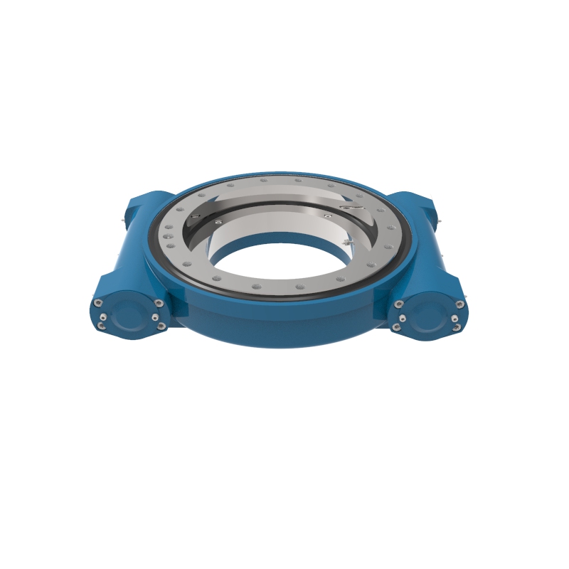
Double Worm Slewing Drive WED14
The WED14 double worm slewing drive uses two worms on one wheel for higher torque and retention, with same mounting size as WE14 series.
Read More Get A Quote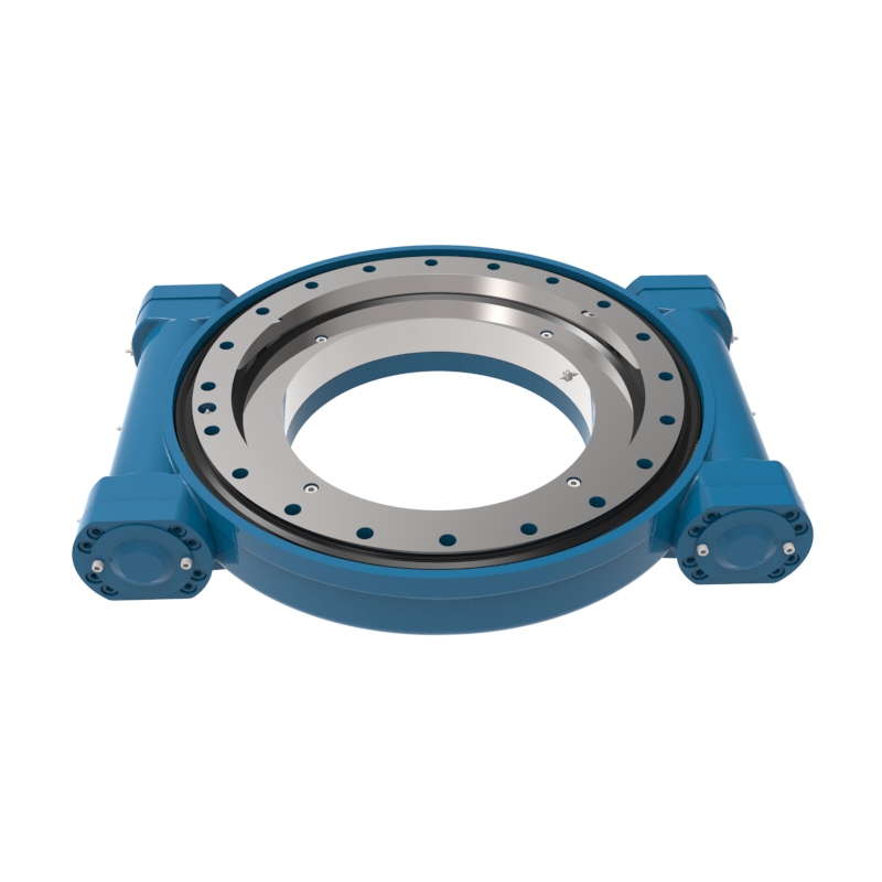
Double Worm Slewing Drive WED17
The WED17 double worm slewing drive delivers 9.45 kN·m in a compact design for high-torque, space-limited applications.
Read More Get A Quote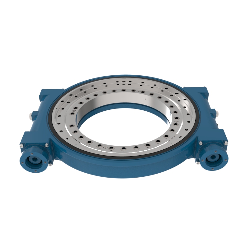
Double Worm Slewing Drive WED21
The WED21 double worm slewing drive delivers 48 kN·m via dual-worm design for heavy machinery in construction, mining, energy, marine, and automation.
Read More Get A Quote
Double Worm Slewing Drive WED 25
The WED25 double worm slewing drive drives one wheel with two worms, delivering higher torque in a compact, heavy-duty design.
Read More Get A Quote
What Is a Double Worm Slew Drive?
A double worm slew drive is an advanced, heavy-duty integrated rotation system designed for applications that demand extreme torque and uncompromising load-holding stability. While a standard slew drive utilizes a single worm shaft, this configuration integrates two worm shafts positioned at opposing points around a single, robust slewing ring gear. By engaging the internal or external teeth of the gear from two contact areas simultaneously, it acts as a highly rigid speed reducer and structural bearing capable of managing massive, multi-directional forces within a remarkably compact footprint.
Key Features of Double Worm Slew Drives
Increased Load Capacity: By distributing the load between two worms, these drives can handle significantly higher axial and radial loads, making them suitable for heavy-duty applications.
Enhanced Accuracy and Precision: Double worm slewing drives offer improved positional accuracy and smoother movement, which is critical in applications requiring precise motion control.
Reduced Backlash: Backlash, or the clearance between the gear teeth, is minimized in double worm configurations. This is crucial for applications where the precision of movement is essential.
Improved Stability and Rigidity: The dual contact points provide better stability and rigidity under load, reducing the risk of deflection and ensuring consistent performance.
Extended Lifespan: The load distribution also reduces the wear and tear on each worm, potentially extending the life of the slewing drive.
How Does a Double Worm Slew Drive Work?
The operation of a double worm slew drive relies on synchronized, dual-point mechanical engagement:
Synchronized Input: An external power source (either dual synchronized electric/hydraulic motors or a single motor split via a driving mechanism) rotates both worm shafts at identical speeds.
Dual-Mesh Torque Multiplication: As both worm shafts spin, their helical threads drive the large slewing ring gear from two different sides at once. This dual engagement creates a massive gear reduction ratio, converting high-speed input into immense, multiplied rotational output torque.
Balanced Load Distribution: Because the driving forces are applied at two separate contact points, the internal stresses and separation forces are balanced across the slewing ring, resulting in exceptionally smooth rotation and vastly reduced localized wear on the gear teeth.
The Difference Between Double and Single Worm Slew Drives
While standard single-worm drives are excellent for cost-effective, everyday applications, a double worm configuration introduces distinct mechanical differences:
Torque Capacity: By utilizing two points of contact instead of one, the double worm design delivers up to twice the rotational and output torque of a standard single-worm drive within the exact same footprint.
Load Distribution: A single worm drive concentrates all driving forces on one small section of the gear. A double worm drive distributes the mechanical workload across two separate shafts, halving the stress on individual gear teeth and significantly extending service life.
Holding & Braking Power: The dual-mesh configuration drastically increases the drive's static holding torque and enhances its reverse self-locking safety performance, preventing dangerous unpowered back-driving under heavy shock loads or high winds where a single worm drive might struggle.
| Comparison Factor | Single Worm Slew Drive | Double Worm Slew Drive |
|---|---|---|
| Torque Output | Standard rotational torque output. | Doubled torque output (up to 2x) within the same footprint. |
| Load Distribution | Concentrated on a single gear-mesh contact point. | Balanced across two separate shafts, halving individual tooth stress. |
| Holding Capacity | Standard static holding torque; vulnerable to extreme shock loads. | Superior holding torque, drastically improving resistance to external shocks or high wind loads. |
| Self-Locking Safety | Relies on a single worm interface for passive braking. | Enhanced reverse self-locking safety with dual-point mechanical gripping. |
| Service Life | Standard wear cycle on the single contact area. | Extended service life due to significantly reduced localized gear wear. |
| Best Application | Cost-effective, standard-load everyday applications. | Extreme high-torque, heavy-duty, and safety-critical environments. |
How to Select a Double Worm Slew Drive?
When selecting a double worm configuration for your project, evaluate the following five core engineering criteria:
Load Requirements
Quantify the simultaneous combination of axial loads, radial loads, and especially the tilting moment (overturning force) created by cantilevered payloads. Ensure the combined static and dynamic load profiles fall safely within the manufacturer’s dual-contact performance curves.
Speed and Efficiency
Double worm drives are built for high-torque, low-RPM operations. Determine your required duty cycle (continuous vs. intermittent) to ensure proper thermal dissipation, and verify that the drive's self-locking capabilities match your application's passive braking requirements.
Precision and Backlash
Evaluate the precision demands of your positioning system. Because double worm designs naturally minimize rotational clearance, they are ideal for applications requiring low backlash and highly stable positioning accuracy under changing load directions.
Environment & Space
Assess the operational environment to choose the right ingress protection (such as fully enclosed IP65/IP66 housings for rugged outdoor or mining use). Additionally, leverage the drive's compact, dual-shaft footprint to maximize power density in spatial layouts where a larger single-worm drive would not fit.
Material & Cost
Specify the necessary surface treatments—such as specialized protective coatings, zinc plating, or stainless steel components—to resist corrosion in harsh marine or chemical environments. Balance the initial investment against the long-term cost efficiencies gained from reduced structural engineering hours, a simplified supply chain, and minimal maintenance overhead.
Primary Applications of Double Worm Slew Drives
Double worm slewing drives are particularly useful in applications that require robust performance, high precision, and substantial load-bearing capacity:
Heavy-Lift Utility Cranes & Marine Hoists
Designed to handle the most demanding lifting environments, these drives manage the extreme overturning moments and heavy structural weight of large truck-mounted cranes, boom trucks, and offshore marine davits.
Large-Scale & Dual-Axis Solar Arrays
Perfect for massive commercial solar tracking installations where a single-worm drive would buckle under immense wind loads. The dual-contact design ensures stable tracking and reliable wind-resistance for expansive PV arrays and concentrated solar power (CSP) mirrors.
Rugged Construction & Mining Machinery
Widely integrated into the heavy rotation mechanisms of multi-function grab machines, demolition equipment, excavators, and drilling rigs that operate under continuous shock loads and harsh, high-debris working conditions.
Heavy-Duty Industrial Automation & Rotary Tables
Utilized in large-scale factory assembly lines, heavy foundry equipment, and massive indexing rotary tables where enormous rotational torque and rigid, zero-slip precision are required to move heavy payloads.
Aerial Work Platforms & Fire Truck Ladders
Critical for high-reach applications like telescopic boom lifts and fire engine ladder turntables, where maximum structural stability and uncompromising self-locking safety performance are mandatory to protect personnel at height.
Deep-Space Satellite & Radar Positioning
Deployed in large-scale satellite communication dishes, telemetry antennas, and military radar tracking systems to maintain rock-solid alignment and zero-backlash positioning, even when fighting severe, high-altitude crosswinds.
Double Worm Slew Drive Installation and Operation Manual
Important: Before installing the Double Worm Slew Drive, please read this manual carefully. This manual provides critical information for proper installation and maintenance procedures. All installation and maintenance work must be performed by qualified technicians. For any technical inquiries, please contact our after-sales service department immediately.
During transportation, ensure the Double Worm Slew Drive is properly secured in its packaging with correct orientation to prevent impacts or shocks. Always use appropriate lifting equipment with at least three lifting points attached to the designated threaded holes on the housing. Personnel must wear protective gloves during handling operations.
Store the Double Worm Slew Drive in its original packaging in a clean, dry and well-ventilated environment. The factory-applied anti-corrosion protection remains effective for 6 months when kept in sealed packaging. For extended storage periods exceeding 6 months, additional protective measures must be implemented.
Pre-Installation & Surface Preparation
Thoroughly inspect the Double Worm Slew Drive for any visible damage before installation. Clean all mounting surfaces and adjacent components, removing any contaminants including metal particles, burrs, paint residue or welding slag that may affect installation. Remove anti-corrosion coatings from mounting surfaces using approved solvents (mineral spirits or equivalent). Avoid solvents that may damage rubber seals or other non-metallic components. Always follow solvent manufacturer's safety guidelines.
Fastener Selection Guidelines
Note: Our company does not provide installation fasteners. The following are recommendations only: Select fasteners meeting specified size, type and strength requirements. Minimum bolt grade requirement: 8.8. Required thread engagement: 2 × nominal bolt diameter. Prevent fastener protrusion beyond threaded areas. For high stress applications, use appropriate high-strength washers.
Recommended Tightening Torques (Values in N·m)
| Bolt Size | 8.8 Grade | 10.9 Grade | 12.9 Grade | Bolt Size | 8.8 Grade | 10.9 Grade | 12.9 Grade |
|---|---|---|---|---|---|---|---|
| M5 | 5.6 | 8.2 | 9.6 | M16 | 230 | 338 | 395 |
| M6 | 9.8 | 14.4 | 16.8 | M18 | 320 | 470 | 550 |
| M8 | 24 | 35 | 41 | M20 | 450 | 660 | 772 |
| M10 | 48 | 70 | 82 | M22 | 600 | 880 | 1030 |
| M12 | 83 | 122 | 143 | M24 | 800 | 1175 | 1375 |
| M14 | 130 | 191 | 224 | M27 | 1150 | 1690 | 1975 |
Installation Procedure
Follow this sequence to ensure proper installation: Apply medium-strength thread locker to all fasteners. Tighten bolts in a star pattern in three stages: First pass: 30% of final torque. Second pass: 60% of final torque. Final pass: 100% of specified torque. All bolt holes must be filled. If design constraints prevent this, seal unused holes with silicone to prevent contamination. Verify no fastener interference with rotating components. Mark fastener positions for future maintenance reference.
Lubrication Specifications
The Double Worm Slew Drive is pre-lubricated with high-performance grease (Shell Gadus S2 V220 or equivalent). Additional lubrication may be required during installation: Worm gear meshing surfaces: Pre-lubricated. Bearing assemblies: Pre-lubricated. Sealing surfaces: Light coating recommended.
Maintenance and Re-Lubrication Schedule
Service intervals vary based on operating conditions. Conduct regular inspections to determine optimal maintenance frequency. Recommended baseline intervals:
| Operating Environment | Service Interval |
|---|---|
| Light duty (indoor, clean conditions) | 12-18 months |
| Standard industrial applications | 6-12 months |
| Heavy duty (construction, mining) | 3-6 months |
| Extreme conditions (marine, high dust) | 1-3 months |
Note: For continuous operation exceeding 50 hours/week, reduce intervals by 30%. Always inspect lubrication condition during routine maintenance.
Safety Considerations
⚠️ Never operate the drive without proper lubrication.
⚠️ Always disconnect power before performing maintenance.
⚠️ Use only recommended lubricants and replacement parts.
⚠️ Record all maintenance activities in the service log.
⚠️ For technical support or additional documentation, please contact our engineering department.
Can't find a slew drive that fits your needs? Our team of engineers can design a slew drive unique to your application. To learn more about our products, including slew drive price, request a quote or contact us directly.