



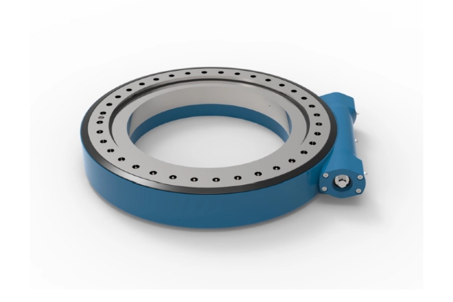
What is a slew drive for crane rotation? It is a ready-to-install rotary assembly that combines a slewing bearing, gear set, housing, and mounting interfaces to rotate a crane boom, platform, deck crane, or lifting attachment.
The selection challenge is not simply choosing the largest unit. Crane OEM engineers and retrofit buyers must match the drive to overturning load moment, operating output torque, holding torque, rotation speed, mounting geometry, and environmental exposure. A drive that produces enough turning force may still be the wrong choice if it cannot safely hold the structure against wind, suspended-load effects, or cyclic loads when the motor stops.
For most crane applications, start with the maximum combined load case rather than the empty-crane condition. Then compare the calculated demand against the supplier’s rated limits for axial load, radial load, overturning moment, output torque, and holding torque. If the crane duty includes frequent starts, reversing motion, or off-center lifting, a larger bearing and gear margin may be needed even when the nominal turning torque appears acceptable.
Start with the crane load case, not the drive catalog size
The first decision is whether the rotation assembly must mainly carry a modest platform load or resist high overturning moment from a boom and suspended load. This distinction changes the bearing arrangement, housing strength, gear configuration, and gearbox ratio. Selecting from outside diameter alone is unreliable because two units of similar physical size can have very different load paths and torque ratings.
Calculate load moment from the force acting on the rotating structure multiplied by its horizontal distance from the rotation center. Include the boom, hook block, suspended load, attachments, and any offset caused by the center of gravity. Wind and dynamic motion may also increase the design condition, especially for outdoor utility cranes and marine equipment.
- Axial load: The vertical force transmitted through the turntable. This is often high when the crane supports a boom, mast, platform, or suspended equipment.
- Radial load: The side force acting across the rotation axis. It rises when a load pulls sideways, the vehicle is on uneven ground, or the crane structure is exposed to lateral forces.
- Overturning moment: The tipping force caused by a load acting away from the centerline. This is often the governing criterion for boom cranes.
- Output torque: The torque required to begin and maintain rotation under the selected operating condition.
- Holding torque: The resistance needed to prevent unwanted rotation after the drive stops. It must be reviewed separately from output torque.
Choose a compact single-worm arrangement when the calculated moment and duty cycle fall within its verified rating and one drive position is sufficient. Choose a Double Worm Slew Drive when the crane requires better load sharing across two worm engagements, improved resistance to rotational backlash effects, or greater stability under demanding cyclic loading. The double-worm option is not automatically better for every crane; it adds complexity and should be justified by the actual load and accuracy requirement.
For a retrofit, inspect the existing rotation center, bolt circle, mounting-face flatness, motor direction, available installation envelope, and cable routing before selecting the replacement. A technically adequate drive can still create installation problems if its mounting arrangement conflicts with the crane frame or the boom support structure.
Separate operating torque from holding torque before comparing options
Output torque answers one question: can the drive rotate the crane under the selected load condition? Holding torque answers another: can the system resist rotation when stopped? These values should never be treated as interchangeable because the forces acting during movement and during parked or suspended-load conditions can differ.
A worm-driven unit may provide self-locking behavior under certain conditions, but engineers should not use a generic self-locking statement as a complete safety calculation. Worm geometry, friction conditions, lubrication, wear, external vibration, and the applied moment all affect behavior. Confirm the required holding condition with the drive supplier and review whether a mechanical brake, hydraulic brake, or other external holding method is needed.
| Selection factor | What to calculate or verify | When it drives the decision | Limit of using it alone |
|---|---|---|---|
| Operating output torque | Torque needed for starting, accelerating, and rotating the loaded crane structure | Frequent rotation, reversing duty, or high friction in the turntable system | Does not prove that the crane will remain stationary after power is removed |
| Holding torque | External moment that can act while rotation is stopped | Suspended loads, wind exposure, boom offset, and parked equipment | Must be assessed with braking and safety-system design, not only gear data |
| Overturning moment | Combined load moment at the bearing center | Long boom radius, offset payload, and compact mounting footprints | Does not replace the torque check for acceleration and rotation resistance |
| Rotation speed | Required output speed and start-stop frequency | Production cranes, automated turntables, and repetitive positioning work | Higher speed may change motor, ratio, heat, and duty considerations |
For example, a crane can rotate easily while unloaded yet need much higher torque when the boom is offset and the load is lifted. In that case, sizing from unloaded rotation is not valid. Use the worst credible operating position, then ask the supplier to review the calculated combined loads against the assembly rating.
Luoyang Slewring Bearing Co., Ltd. can provide a technical proposal within 24 hours when the application inputs are available. For nonstandard mounting, load direction, or motor interface requirements, a Customized Slew Drive may be more appropriate than forcing a standard assembly into an unsuitable crane structure.
Compare load moment, output torque, holding torque, and gearbox ratio for mobile and utility cranes
The table below is a selection framework, not a substitute for the supplier’s final rating confirmation. It helps procurement teams and design engineers identify which configuration should enter the shortlist. The right choice depends on the highest combined condition, not on a single isolated value.
| Crane condition | Load-moment condition | Output-torque need | Holding-torque focus | Gearbox-ratio direction | Best selection rule |
|---|---|---|---|---|---|
| Light utility crane with short working radius | Lower relative overturning moment | Moderate torque for occasional rotation | Verify parked-load and wind condition | Use a moderate ratio when faster rotation is more valuable than maximum torque multiplication | Choose a single-worm unit only after confirming bearing moment and holding requirements |
| Truck-mounted loader crane with variable outreach | Changes significantly with boom extension and payload position | Higher starting torque may be needed at maximum outreach | High priority because the boom can remain offset while stopped | Use a higher ratio when more output torque and controlled movement are needed | Size from maximum outreach and the most unfavorable rotation position, not average lifting duty |
| Utility service crane with frequent positioning | Moderate to high, depending on boom and attachment configuration | Must suit repeated starts, stops, and reversals | Review holding during elevated work and parked positions | Balance ratio against required output speed and motor capability | Choose the ratio only after defining rotation cycle time and motor speed |
| Heavy mobile crane or high-moment turntable | High combined moment with demanding cyclic loads | High torque demand, especially during loaded starts | High priority; separate external braking review may be needed | Higher ratio is often favored where controlled movement and torque multiplication matter more than speed | Consider a double-worm configuration and verify all combined bearing loads with the supplier |
| Marine deck crane or exposed outdoor crane | Can be affected by boom position and vessel or site movement | Must account for resistance during operating motion | Must account for wind, vibration, and stopped-position forces | Select ratio from the required output speed after torque and holding checks are complete | Specify sealing and corrosion protection with the mechanical duty requirements |
A higher gearbox ratio can increase torque multiplication at the output, but it usually reduces output speed for a given motor speed. Choose it when controlled rotation and torque capacity are the priority. Do not select a higher ratio by default if the crane has a firm rotation-time requirement that the selected motor and ratio combination cannot meet.
A lower ratio may suit applications requiring quicker rotation with a suitably sized motor. Its limit is that it may not provide enough torque margin for loaded starts or high-resistance conditions. The correct ratio is therefore a system decision involving motor characteristics, desired output speed, load moment, duty cycle, and gear-drive rating.
Request Your Custom Slew Drive or Bearing Spec
Tell us your load, speed, and environment — receive a tailored 100–5000 mm slewing drive or slewing bearing proposal with 3D drawings within 24 hours.
Choose single-worm, double-worm, or separate bearing-and-drive layouts
A ready-to-install Worm Gear Slew Drive is often preferred when the crane needs a compact integrated assembly. It combines the bearing and reduction function in one housing, which can simplify mounting and reduce the number of separately matched components. It is a good fit when the available space is limited and the supplier can verify the full load case.
Single-worm configurations can fit cranes with one-direction actuation requirements and moderate duty conditions. They are practical when the calculated combined loads, rotation accuracy needs, and holding requirements are within the verified ratings. They may not be the preferred solution when high moment, frequent reversals, or tighter positioning stability call for improved load sharing.
Double-worm designs use two worms engaging the slewing ring gear. This arrangement can be considered for heavy mobile equipment, forestry attachments, and crane systems where backlash control and load distribution matter. Luoyang Slewring Bearing Co., Ltd. supplied WED14-86-25BHR.5 double-worm units to a forestry grapple manufacturer in British Columbia, Canada, for an application requiring precision of no more than 0.13 degrees.
For a crane with an existing large turntable bearing, a separate drive and Slewing Bearing arrangement may be the better retrofit path. This can preserve the established bearing interface while replacing or upgrading the drive system. It does not apply when the current bearing is worn, undersized, or unable to support the new duty condition; then the bearing and drive should be evaluated together.

Check duty cycle, environment, and verification evidence before supplier approval
Crane rotation duty is not defined by maximum load alone. Ask how often the drive starts, stops, reverses, and remains under load. Frequent cyclic operation can change the suitable drive configuration even where the maximum static moment is unchanged.
Environmental conditions should be written into the RFQ. State whether the crane operates indoors, outdoors, in dust, rain, coastal air, or corrosive industrial exposure. Luoyang Slewring Bearing Co., Ltd. offers slew drives with protection up to IP66 and anti-corrosion rating up to C4H, but the selected protection level should match the actual site exposure rather than being copied from another project.
For marine and port use, sealing and corrosion protection deserve the same attention as torque capacity. A drive that fits a sheltered workshop crane may not suit a deck crane exposed to salt-bearing air and weather. The company supplied 20 WEA17-104-25H-R-REV.D units to UK Ocean Marine Systems for marine shipboard crane systems, showing that crane-drive selection can be aligned with marine equipment requirements when the application details are provided.
Quality evidence should also be part of commercial evaluation. Our ISO 9001:2015-certified facility uses CNC machining centers and CMM three-coordinate inspection, and every slewing bearing is subject to CMM inspection and dynamic load testing under the stated quality-control process. Buyers should request the applicable drawings, inspection expectations, material selection basis, and load-rating confirmation for the exact configuration quoted.
Common selection mistakes that create crane rotation problems
- Sizing from payload weight only: Payload without boom radius does not show overturning moment. Include every force and its distance from the rotation center.
- Using output torque as holding torque: A drive that rotates the load may not meet stopped-position requirements. Review external moment and braking needs separately.
- Ignoring the worst boom position: The maximum moment may occur at a specific outreach, jib angle, or attachment position. Use that condition for the primary selection check.
- Selecting ratio before defining speed: A high ratio can improve torque multiplication but may slow crane rotation. Set the output speed target first.
- Copying a previous drive model: A similar crane can have different boom length, mounting stiffness, duty cycle, or environment. Recheck the calculations for every project.
- Skipping interface drawings: Bolt patterns, mounting surfaces, motor adapters, rotation direction, and clearance zones must be confirmed before production.
Prepare an RFQ that allows a technically valid crane-drive recommendation
A short RFQ with incomplete load information can lead to a catalog-level recommendation rather than an application-specific selection. Provide enough data for the supplier to review both bearing loads and gear-drive demands. This is especially important for retrofit projects where the original crane drawings may be incomplete.
- Describe the crane type, such as truck-mounted crane, utility crane, deck crane, service crane, or rotating lifting platform.
- Provide the maximum payload, boom or load radius, rotating-structure weight, and center-of-gravity location where available.
- State axial load, radial load, and overturning moment calculations if they have already been completed.
- Define required output speed, motor type, motor speed, rotation direction, and expected start-stop frequency.
- Identify the required holding condition, including whether loads can remain suspended or offset while rotation is stopped.
- Share mounting drawings, bolt-circle information, available envelope, and preferred motor connection.
- State the operating environment and any sealing or corrosion-protection requirement.
- Request drawings and technical confirmation for the exact proposed assembly before final approval.
Standard product orders can start from one set, while customized product orders have a minimum order quantity of five sets. Luoyang Slewring Bearing Co., Ltd. also welcomes sample orders for testing and evaluation, which can help OEM teams confirm installation fit and operating behavior before a larger production release.
Choose a single-worm assembly when verified load moment, torque demand, holding conditions, and duty remain within its rating. Choose a double-worm arrangement when the crane needs greater stability under demanding cyclic loads, better load sharing, or tighter control of rotation behavior. If the existing crane uses a separate bearing and drive, first determine whether the current turntable remains suitable; if it does not, evaluate the complete rotating assembly instead of replacing only the gearbox.
Request Your Custom Slew Drive or Bearing Spec
Tell us your load, speed, and environment — receive a tailored 100–5000 mm slewing drive or slewing bearing proposal with 3D drawings within 24 hours.
 WhatsApp

 +8613903880726