



What is a slew drive? It is a geared rotary unit that combines a slewing bearing, gear set, housing, and drive interface to rotate a structure under axial load, radial load, and overturning moment. In a crane, it must do more than turn the boom. It must control rotation during lifting, resist changing loads, and help hold the upper structure in a safe parked condition.
The decision is rarely about finding the largest unit. A correctly selected slew drive for crane applications must match the real boom load moment, acceleration demand, duty cycle, wind condition, mounting structure, and holding method. An oversized drive can add unnecessary cost and weight. An undersized drive can create gear wear, bearing damage, poor positioning, or an unsafe holding condition.
Luoyang Slewring Bearing Co., Ltd. supplies Slew Drive assemblies and customized rotary solutions for heavy equipment. For crane projects, the calculation should start with the load case, not with a catalog frame size.

Start With the Crane Conditions That Actually Control Selection
A crane rotary system sees combined loading. The boom and lifted load create overturning moment. The rotating upper structure creates inertia during starting and stopping. Wind can add side force and extra moment. These conditions must be checked together because a drive that can rotate a light boom may still be unsuitable when the same boom carries a lifted load at maximum reach.
The first conclusion is simple: use the worst credible operating position, not a convenient average position. This approach fits preliminary design, supplier comparison, and component validation. It does not replace a full crane stability review or a structural analysis of the crane frame, turntable, fasteners, and bearing support surfaces.
| Input to collect | Why it affects the drive | What to verify | Limit of the input |
|---|---|---|---|
| Lifted load and hook block mass | Creates boom-side overturning moment | Maximum rated lifted condition and load chart position | Do not use nominal load if attachments or rigging are excluded |
| Boom, jib, counterweight, and upper structure mass | Contributes dead-load moment and rotational inertia | Center-of-gravity location at each boom angle | Center of gravity can shift when attachments change |
| Horizontal radius from slew center | Converts weight into overturning moment | Maximum working radius and parked radius | Maximum radius may differ from the highest-load radius |
| Target slew speed and acceleration | Sets acceleration torque and motor demand | Start, stop, reversal, and positioning pattern | Steady rotation torque alone does not cover transient events |
| Wind and parked condition | Can govern brake holding torque | Allowed operating wind and out-of-service wind procedure | Wind design values must come from the crane project requirements |
| Duty cycle | Changes thermal demand, fatigue exposure, and service factor | Starts per shift, loaded rotation time, and idle time | Calendar hours alone do not describe severe cyclic loading |
Keep operating and parked cases separate. An operating case asks whether the drive can rotate the crane under controlled load. A parked case asks whether the complete system can resist external moment without unintended movement. The second case often requires a brake, locking device, restraint procedure, or a combination selected by the crane designer.
Worm gearing is often considered where controlled rotation and holding behavior matter. A Worm Gear Slew Drive may suit compact crane layouts, but self-locking must never be assumed from the gear type alone. Gear geometry, lubrication, wear, vibration, back-driving force, temperature, and the installed motor or brake arrangement must be reviewed for the actual duty.
Convert Boom Load Moment and Duty Cycle Into Torque and Brake Requirements
This worked conversion is an illustrative engineering worksheet, not a completed customer project. It shows the calculation path from crane load data to a supplier requirement. Replace each symbol with project values from the crane load chart, mass model, operating procedure, and site wind criteria.
Begin by separating overturning moment from rotary torque. A boom load moment acts on the bearing and mounting structure. Rotary output torque is the torque needed to overcome resistance and accelerate or decelerate the rotating mass. They are related through the application, but they are not interchangeable ratings.
| Calculation stage | Formula or action | Result used for selection | Selection meaning |
|---|---|---|---|
| Lifted-load moment | Mlift = Wlift × Rlift | Moment from lifted load at the slew center | Use the most severe permitted lifting radius |
| Dead-load moment | Mdead = Σ(Wcomponent × Rcomponent) | Moment from boom, jib, hook block, and other offset masses | Use actual centers of gravity, not assumed midpoint locations |
| Wind moment | Mwind = Fwind × Heffective | Additional overturning moment from exposed area | Apply the project wind load model and parked condition rules |
| Combined bearing moment | Mtotal = Mlift + Mdead + Mwind | Overturning moment for bearing, housing, frame, and bolts | Check with axial and radial loads at the same time |
| Acceleration torque | Tacc = Jtotal × α | Torque to reach commanded slew acceleration | Jtotal includes rotating structure and carried load inertia |
| Resistance torque | Tres = bearing friction + seal drag + gear losses + external resistance | Torque needed during steady motion | Use verified supplier and system values where available |
| Required output torque | Trun = (Tacc + Tres) × SF | Minimum drive output torque target | SF is the service factor selected from duty severity and uncertainty |
| Brake holding torque | Thold ≥ (Texternal) × SFhold | Holding requirement for brake or restraint system | Texternal includes gravity, wind, and possible back-driving torque |
How to choose the service factor from duty cycle
The service factor should reflect how the crane is used, not merely how long it exists on site. A lightly used maintenance crane with smooth starts and long idle periods may need less allowance than a grab crane, marine deck crane, forestry crane, or truck-mounted crane making frequent loaded reversals.
- Use a lower service factor range only when: starts are controlled, loads are predictable, slew acceleration is limited, and the operating environment is stable.
- Increase the service factor when: the crane sees frequent starts and stops, load swing, shock loading, repeated reversals, uneven mounting stiffness, contamination, or uncertain resistance torque.
- Use a separate holding factor when: the parked case includes wind, an elevated boom, suspended equipment, or a possible back-driving load path.
- Do not use service factor as a substitute for missing data: unknown center of gravity, missing wind criteria, or unverified inertia should be resolved before final selection.
The clear recommendation is to send both Mtotal and Trun to the drive supplier. Sending torque alone can hide the bearing and mounting moment. Sending moment alone can hide acceleration and motor demand. A valid component review needs both.
For two-sided support or applications with high moment demand, a Double Worm Slew Drive can be considered. Its fit depends on the load arrangement, target positioning behavior, mounting envelope, and available motor layout. It is not automatically the right choice for every crane; a simple, lower-duty crane may be better served by a different configuration.
Request Your Custom Slew Drive or Bearing Spec
Tell us your load, speed, and environment — receive a tailored 100–5000 mm slewing drive or slewing bearing proposal with 3D drawings within 24 hours.
Validate the Bearing, Gear, Brake, and Mounting Interfaces as One System
The output torque calculation is only one gate. The drive housing transfers load into the mounting structure, while the internal bearing carries axial force, radial force, and overturning moment. A high torque rating does not prove that the bearing or support frame is adequate.
Use the following validation sequence before approving a proposed assembly.
- Build the load table. List operating, acceleration, braking, parked, transport, and maintenance positions. Identify the governing combination of axial load, radial load, overturning moment, and torque.
- Confirm the rotation profile. Define speed, acceleration, deceleration, reversal frequency, and allowable backlash or tracking requirement.
- Review bearing capacity. Ask for confirmation against the combined load case, not against isolated axial or moment values.
- Check the gear train. Compare required continuous and peak torque with the available output torque for the stated duty and lubrication condition.
- Size the brake or restraint. Evaluate external torque in the parked position. Confirm whether a motor brake, mechanical lock, hydraulic restraint, or site procedure is required.
- Verify the mounting structure. Check flatness, bolt pattern, bolt preload method, stiffness, and access for inspection. A flexible base can change bearing load distribution.
- Review environmental protection. Match sealing and corrosion needs to salt spray, dust, rain, washdown, or desert exposure.
- Document acceptance checks. Define inspection records, functional tests, torque verification, and traceability before production release.
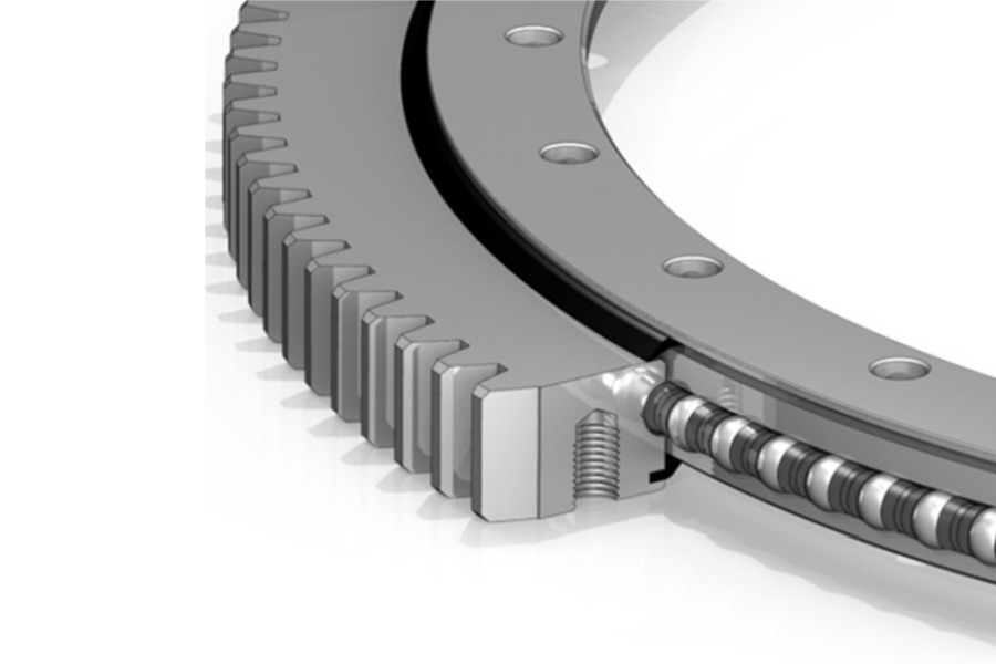
Where the crane structure needs a separate large-diameter ring rather than an enclosed drive, a Slewing Bearing can be assessed as part of a geared turntable system. Heavy moment applications may also require review of a Heavy load slewing bearing rather than selecting by drive torque alone.
Luoyang Slewring Bearing Co., Ltd. has an ISO 9001:2015 quality management system and uses CMM three-coordinate inspection in its manufacturing process. For a crane component review, those controls matter because dimensional accuracy, gear engagement, mounting interfaces, and inspection records affect how closely the delivered assembly matches the approved design basis.
Use Recorded Crane Cases as Reference Points, Not Direct Substitutes
Real applications can help a buyer ask better questions, but a case does not transfer automatically to a different crane. Load chart, boom geometry, duty cycle, motor selection, frame stiffness, and wind exposure can change the required configuration.
One recorded example involved a South Korean port equipment manufacturer that placed a repeat order for WEA9-62-25HR single worm slew drives for port crane systems. The documented configuration included IP65 sealing, self-locking behavior, and tracking precision of no more than 0.15 degrees. This supports the relevance of a sealed worm-drive arrangement for that specific port crane application. It does not prove that the same model is suitable for another crane without reviewing its load moment and holding case.
Other recorded crane-related deliveries include WEA17-104-25H-R-REV.D units for UK Ocean Marine Systems shipboard crane systems, WEA9-61-25HR worm gear units for ship deck cranes in Newcastle, Australia, and WEA9-62-25HR units for truck-mounted loader cranes in the Netherlands. These examples show use across marine and mobile crane contexts. They do not provide a universal torque, wind, or load rating for future projects.
For projects with unusual mounting dimensions, special motor interfaces, dual-drive arrangement, or nonstandard corrosion exposure, a Customized Slew Drive review is more appropriate than forcing a standard model into the layout. Luoyang Slewring Bearing Co., Ltd. accepts customized-product orders from five sets and offers technical proposals within twenty-four hours based on supplied application data.
Know When a Standard Drive Is Not Yet Ready for Approval
A standard unit is not ready for release when the buyer cannot provide a defined maximum load moment, rotation profile, mounting drawing, or holding method. These gaps are not minor paperwork issues. They directly affect bearing selection, gear torque, brake sizing, and support-frame design.
- Do not approve by motor power alone. Motor power may indicate available motion energy, but it does not confirm output torque, gearbox ratio, bearing capacity, or brake holding torque.
- Do not equate self-locking with a complete safety brake. The crane designer must check all external torque paths, vibration, wear, and site requirements.
- Do not use static boom moment as the only load case. Acceleration, deceleration, wind, and rotating inertia can change the required drive torque.
- Do not ignore transport and installation loads. These conditions can load the assembly differently from normal lifting operation.
- Do not approve the drive before checking bolt joints and support stiffness. The drive and crane frame operate as one load path.
Luoyang Slewring Bearing Co., Ltd. operates six production lines in an 8,000 square meter manufacturing facility and has an annual capacity of 100,000 sets. Standard products can be ordered from one set, which helps engineering teams validate a proposed configuration before a larger release. Sample orders are also available for testing and evaluation.
Prepare a Supplier Package That Produces a Useful Technical Proposal
A good request for quotation should allow the supplier to assess the application, not just quote a model number. The stronger the input package, the easier it is to compare proposals on capacity, configuration, delivery, and risk.
| Send to the supplier | Why it is needed | Decision it supports |
|---|---|---|
| Crane arrangement drawing | Shows slew center, load path, clearances, and mounting envelope | Housing orientation and mounting feasibility |
| Maximum combined load table | Provides axial, radial, and overturning loads | Bearing and housing assessment |
| Required output torque calculation | Shows running, acceleration, and deceleration demand | Gear ratio and drive selection |
| Duty cycle description | Shows starts, stops, reversals, and loaded rotation frequency | Service factor and thermal review |
| Parked-load and wind requirements | Defines external holding torque | Brake, lock, or restraint review |
| Environmental requirements | Defines sealing and corrosion needs | Protection configuration selection |
| Motor, hydraulic, or electric interface | Defines input speed, connection, and control method | Integration and commissioning plan |
Our protection options can reach IP66, with anti-corrosion protection up to C4H when the selected design and working condition require it. Those ratings should be matched to the actual project specification, especially for port and marine crane equipment. They should not be treated as automatic requirements for every indoor crane.
The final approval target is clear: the selected assembly must carry the combined bearing loads, deliver the required operating torque, tolerate the planned duty, fit the mounting structure, and provide a verified method for holding external parked loads. When those checks are documented together, the crane team can move from a preliminary load moment to a defensible component decision.
Request Your Custom Slew Drive or Bearing Spec
Tell us your load, speed, and environment — receive a tailored 100–5000 mm slewing drive or slewing bearing proposal with 3D drawings within 24 hours.
 WhatsApp

 +8613903880726