



What is a slew drive for excavator attachment? It is a compact rotation unit that combines a slewing bearing, gearing, and a drive input to turn an attachment such as a grapple, auger, screening bucket, crusher, or rotating work tool. It must carry load while allowing controlled rotation under changing hydraulic demand.
When an attachment-mounted drive becomes hot, develops more free play, or rotates slowly, the visible symptom does not confirm the cause. The fault may come from excessive attachment load, poor lubrication, hydraulic restrictions, mounting distortion, gear wear, or a drive that is too small for the real operating cycle.
The goal is to separate those causes before removing the unit or ordering a replacement. A maintenance team that checks the hydraulic supply first may avoid replacing a mechanically sound drive. On the other hand, a team that keeps operating through rising heat and growing backlash may turn a repairable issue into damage to the worm gear, bearing raceway, or mounting structure.
Start with the symptom and build a usable fault record
Begin with observable facts, not assumptions. “The drive is overheating” is not enough for a service report. Record when the heat appears, whether it occurs during loaded rotation or unloaded rotation, whether motion is slow in both directions, and whether the attachment position drifts after stopping.
The first inspection should be done with the machine parked safely, the attachment supported, and the work area cleaned enough to see leaks, loose fasteners, and damaged hose routing. Do not open a drive housing or loosen structural mounting bolts while the attachment is suspended or hydraulically loaded.
Record these conditions before changing parts
- Operating condition: Note whether the issue appears only with a loaded bucket, grapple, auger, or tool, or also when the attachment rotates without material load.
- Direction of rotation: Compare clockwise and counterclockwise performance. A fault in one direction can point toward a hydraulic valve, hose restriction, motor issue, or directional gear loading condition.
- Heat location: Identify whether heat is strongest near the hydraulic motor, worm housing, bearing area, hose fittings, or mounting interface.
- Rotation behavior: Note slow starts, surging, stalls, intermittent movement, noise, vibration, or sudden changes in speed.
- Backlash behavior: Mark the attachment position, then gently reverse direction under controlled conditions. Compare free movement with previous service records or a known-good unit of the same design.
- Lubrication evidence: Look for dry grease points, contaminated grease, water entry, leaking seals, or grease pushed out around damaged sealing areas.
- Recent changes: Record attachment modifications, a heavier tool, longer extension bracket, new hydraulic motor, altered relief settings, impact damage, or changed work cycle.
This record helps distinguish a new fault from normal wear. It also gives the supplier or attachment OEM usable information if technical support is needed. Luoyang Slewring Bearing Co., Ltd. provides a technical proposal within 24 hours and a 48-hour technical response, but a clear fault record makes remote diagnosis much more efficient.
Check hydraulic and external causes before diagnosing internal gear damage
Slow rotation is often blamed on the drive itself. That is a common mistake. A slew drive cannot create its rated rotation performance if the hydraulic motor receives insufficient flow, if return pressure is excessive, or if a control valve is restricting one direction.
Check the accessible hydraulic system first. This is the best sequence when the attachment was previously operating normally and the rotation issue appeared suddenly. It does not replace internal drive inspection when metal contamination, severe noise, or major backlash is already present.
| Observation | What it may indicate | Next check | Limit of the finding |
|---|---|---|---|
| Slow rotation in both directions | Low available hydraulic flow, motor wear, system pressure issue, or internal mechanical drag | Compare supply and return condition with the machine service specification; inspect filters and hose routing | Does not prove the drive is mechanically healthy |
| Slow rotation mainly in one direction | Directional valve issue, restricted hose, damaged fitting, or direction-specific loading | Inspect both hydraulic paths and compare movement with no attachment load | A worn worm gear can also behave differently under reversed load |
| Motor area becomes hot before housing area | Hydraulic inefficiency, high return restriction, incorrect motor condition, or sustained relief-valve operation | Check motor operation and hydraulic circuit against the attachment documentation | Heat can transfer into the drive during long work periods |
| Housing becomes hot during loaded turning | High mechanical resistance, insufficient lubrication, overload, mounting distortion, or duty-cycle mismatch | Inspect lubrication, attachment load, mounting flatness, and backlash trend | Heat alone cannot identify which internal part is affected |
| Attachment stalls while hydraulic system sounds loaded | Excessive external load, mechanical binding, relief setting issue, or drive damage | Stop repeated stall attempts and inspect load condition before further testing | Do not treat stalling as proof of a failed bearing |
Inspect hose condition and routing at full attachment movement. A hose that twists, kinks, or contacts a bracket can restrict flow only at certain rotation positions. This can look like a gear problem because the attachment slows at the same angle each cycle.
Also inspect the mounting interface. Loose bolts, distorted plates, weld repairs, or an uneven adapter can misalign the drive housing and bearing support. Tightening bolts without checking the mounting faces may hide the issue briefly while increasing internal stress.
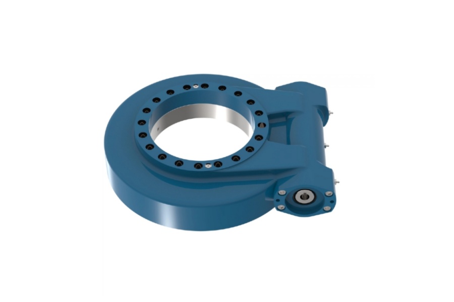
For replacement planning, determine whether the attachment uses a self-locking worm arrangement, a higher-speed gear arrangement, or a more stable dual-worm layout. A Worm Gear Slew Drive is often selected where controlled positioning and holding behavior matter, while a different arrangement may suit applications with different speed and load requirements.
Use heat, backlash, and slow rotation to identify an undersized or overworked drive
Rising temperature, backlash growth, and slow rotation form a useful warning pattern when they appear together. One symptom by itself may have several causes. The combination is more serious because it can show that the unit is operating beyond its intended duty cycle or that the applied load is greater than the drive was selected to carry.
The right response is not to declare the drive undersized after one hot shift. Confirm whether the condition repeats under the same load, whether it worsens over time, and whether the hydraulic supply remains normal. A drive can also overheat because lubrication has failed or because the mounting structure is forcing the bearing out of alignment.
| Trend to watch | Likely interpretation | Practical decision | When to escalate |
|---|---|---|---|
| Heat rises only during unusually heavy digging, lifting, or side loading | The work condition may exceed the normal design load or moment | Review attachment load, center of gravity, and operating cycle before selecting a larger drive | Escalate if the same heat pattern occurs during normal rated work |
| Heat rises during routine work and remains after the attachment is unloaded | Internal friction, lubrication condition, misalignment, or hydraulic inefficiency may be increasing | Inspect grease condition, seals, mounting faces, and hydraulic circuit | Stop operation if noise, smoke, leakage, or severe binding accompanies the heat |
| Backlash grows gradually after repeated high-load cycles | Gear contact or bearing support may be wearing under cyclic load | Compare measured free movement with the original acceptance record or OEM limit | Escalate when free play affects attachment placement, safety, or structural loading |
| Slow rotation appears after the housing gets hot | Increasing friction or heat-related hydraulic loss may be reducing usable rotation performance | Check hydraulic supply and inspect the drive for drag, contamination, and lubrication loss | Do not continue repeated loaded rotation tests to “clear” the fault |
| Slow rotation, rising heat, and growing backlash occur together | The drive may be overloaded, worn, poorly lubricated, or beyond its duty cycle | Remove the attachment from heavy service and begin a documented engineering review | Use supplier or OEM review before choosing a replacement size |
A drive may be undersized even when it can rotate the attachment during a short workshop test. Field use adds shock loading, off-center loading, cyclic reversal, contamination, and long periods under load. A selection based only on static attachment weight can miss the overturning moment created by a long grapple, a full bucket, or material held away from the rotation center.
This is where application information matters. For a mining excavator application, Luoyang Slewring Bearing Co., Ltd. supplied HWE21-94-25HR.1 double worm slew drives to an Australian heavy equipment manufacturer. That case supports the use of a dual-worm configuration for a demanding excavator-related application, but it does not mean that every attachment needs a double-worm unit. The correct choice still depends on actual load, speed, duty cycle, mounting geometry, and required control accuracy.
When the load is high and position stability matters, review whether a Double Worm Slew Drive is more suitable than the existing configuration. This is a sizing discussion, not an automatic repair method. A double-worm design will not correct low hydraulic flow, a bent mounting plate, or contaminated lubrication.
Request Your Custom Slew Drive or Bearing Spec
Tell us your load, speed, and environment — receive a tailored 100–5000 mm slewing drive or slewing bearing proposal with 3D drawings within 24 hours.
Follow a diagnosis order that avoids unnecessary replacement
Use a controlled sequence. Start with checks that are accessible to the maintenance team, then move toward component removal or engineering review only when the evidence supports it. This approach reduces downtime and prevents a hydraulic fault from being mistaken for internal gear failure.
- Confirm the complaint. Run the attachment through a controlled unloaded and loaded movement, if safe. Identify whether slow rotation, noise, heat, or backlash occurs in one direction or both.
- Inspect for external damage. Check hoses, fittings, electrical connections where applicable, mounting bolts, adapter plates, grease points, seals, and visible housing damage.
- Check the hydraulic circuit. Compare supply, return, valve operation, and motor behavior with the machine and attachment service documentation. Look for restrictions that appear at certain attachment positions.
- Inspect lubrication condition. Follow the attachment or drive lubrication procedure. Dirty, dry, or water-contaminated grease can increase friction and speed wear.
- Assess backlash trend. Compare current free movement with installation records, prior inspection records, or a known-good unit. A trend is more useful than an isolated observation.
- Review the work cycle. Identify changes in tool weight, material density, boom reach, rotation frequency, shock loading, or attachment modifications.
- Decide whether the drive is still serviceable. If rotation remains stable after hydraulic and lubrication corrections, continue monitored service. If heat, backlash, and slow rotation remain linked, suspend heavy-duty work and request engineering review.
The verification step matters. After a corrective action, repeat the same safe operating test and compare the result with the original record. If cleaning a restricted hose restores speed but heat and backlash continue increasing, the hydraulic restriction was not the only problem.
A replacement should match the real duty, not merely the envelope dimensions of the removed unit. Provide mounting dimensions, attachment weight, center-of-gravity distance, hydraulic motor details, rotation speed requirement, direction of loading, operating environment, and photos of the failed installation. When standard geometry does not fit the attachment frame or required load condition, a Customized Slew Drive may be the better route.
Know when to stop field troubleshooting and request engineering support
Stop repeated operation and escalate when the attachment shows severe binding, grinding noise, visible metal debris, uncontrolled movement, damaged mounting bolts, cracked structure, or an increasing temperature pattern combined with loss of rotation control. These signs may involve more than the drive itself. Continued use can transfer abnormal loads into the attachment frame, excavator coupler, or hydraulic motor.
Escalation is also appropriate when the unit has been replaced before and the same fault returns. Repeated failures can indicate a selection issue, installation issue, or work-cycle mismatch rather than a defective replacement part. Do not assume every worn drive is a manufacturing defect, and do not assume every failure is caused by operation.
Send these details for a useful technical review
- Photos and video of the attachment during the affected rotation direction
- Drive model identification and installation orientation
- Attachment type, tool weight, and any added bracket or extension
- Operating material and work cycle description
- Hydraulic motor and circuit information from the machine documentation
- Heat location, noise description, leakage evidence, and backlash observations
- Mounting bolt condition, mounting-face photos, and visible structural damage
- Lubrication history and photos of grease condition where available
Luoyang Slewring Bearing Co., Ltd. has operated since 2012 with six production lines and an 8,000 m² manufacturing facility. Its engineering team can review selection inputs for Slew Drive, Slewing Bearing, and customized drive applications. Material selection can include ductile cast iron, alloy steel, stainless steel, or forged alloy steel according to load, speed, and environment.
Quality verification should be part of replacement planning, especially after a field failure. Our ISO 9001:2015-certified facility uses CNC machining centers and CMM three-coordinate inspection. For bearing-related production, every slewing bearing passes CMM three-coordinate inspection and dynamic load testing; see our Slew Drive Quality Control information for the inspection approach.
For suitable confirmed manufacturing defects, Luoyang Slewring Bearing Co., Ltd. provides free replacement and a 2-year extended quality warranty. That warranty does not remove the need to investigate hydraulic restrictions, overload, incorrect mounting, or unsuitable duty cycle before installing the next unit.
Prevent repeat heat and rotation faults through selection and service controls
The best prevention method is to match the drive to the real attachment duty. Use the heaviest expected tool condition, the farthest load center, expected rotation frequency, and operating environment in the selection review. A drive that works on a light demonstration attachment may not be suitable for a production tool handling wet material, impact loads, or long off-center loads.
Set a repeatable inspection routine. Check mounting security, grease condition, seal condition, hose routing, abnormal noise, and free play trends at planned service intervals set by the attachment documentation. The goal is to find change early, before heat and backlash become a combined failure pattern.
For sourcing teams, standard products are available from a minimum order quantity of one set, while customized products start from five sets. Sample orders are welcome for testing and evaluation. Standard production is listed at nine days, while rapid prototyping is available in three days for applicable development work.
A careful diagnosis protects both uptime and replacement budget. Check hydraulic supply and mounting condition first, track heat and backlash as trends, and treat slow rotation as a symptom that needs evidence. When those three signs rise together under normal duty, pause heavy service and review whether the existing drive is worn, misapplied, or too small for the attachment’s actual work cycle.
Request Your Custom Slew Drive or Bearing Spec
Tell us your load, speed, and environment — receive a tailored 100–5000 mm slewing drive or slewing bearing proposal with 3D drawings within 24 hours.
 WhatsApp

 +8613903880726