



What is a slew drive? It is a compact rotary unit that combines a slewing bearing, gear set, housing, and drive input to rotate and hold an attached structure. For an attachment OEM engineer, the selection task is to confirm that the rotary unit can carry the real attachment loads, reach the required rotation speed, and hold position safely when the motor stops.
A slew drive for excavator attachment design should not be selected from the carrier excavator size alone. A small excavator may carry a long-reach attachment with high overturning moment, while a larger carrier may use a compact attachment with modest rotary demand. The attachment geometry and duty cycle decide the drive requirement.
This guide helps engineers and retrofit designers build a selection brief before prototype release or specification approval. The outcome is a clear set of load inputs, mounting requirements, rotation requirements, and verification points that a drive supplier can use for technical selection.
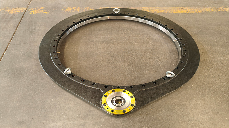
Collect the inputs before comparing drive models
Start with the attachment, not the drive catalog. A catalog model can only be compared after the attachment’s mass distribution, operating position, hydraulic system, and connection layout are known. Missing inputs do not need to stop an early inquiry, but they must be marked as assumptions rather than treated as final design data.
Prepare the following information for the first technical review:
- Attachment mass and center of gravity: Provide the total rotating mass and the distance from the rotation center to the center of gravity. This determines overturning moment and inertia.
- Working radius: Record the farthest operating position of the attachment, tool, payload, or material being handled. Use the loaded condition, not only the empty attachment outline.
- Rotation range and speed: State whether the attachment requires continuous rotation, limited-angle movement, indexing, or frequent reversing. Also state the required cycle time if it is fixed by production needs.
- Holding condition: Identify whether the tool must remain fixed during digging, gripping, lifting, drilling, sorting, or transport. A drive that rotates acceptably may still be unsuitable if its holding behavior is not adequate.
- Hydraulic or electric input: Give available pressure, flow, motor type, mounting space, and hose routing limits. The drive and motor must be considered as one system.
- Mounting interface: Supply bolt-circle drawings, mounting plate thickness, allowable envelope, and load path details. A suitable gear unit cannot correct a weak support frame.
- Environment: Note abrasive dust, water exposure, salt spray, washdown, temperature conditions, and storage conditions. These affect sealing and corrosion protection choices.
The most common early-stage error is using only attachment weight. Weight describes vertical load, but it does not show how far the load acts from the rotation center or how hard it is to start and stop. A long sorting arm, demolition tool, forestry grapple, or drilling assembly can create demanding moment loads even when its total mass appears moderate.
Use a simple drawing to make the data usable. Show the rotation center, attachment center of gravity, tool tip, loaded material position, cylinder forces that pass through the rotating structure, and the direction of possible side loads. This sketch gives the supplier a practical basis for checking the drive rather than guessing from a product photo.
Select by attachment inertia, working radius, and holding torque instead of excavator tonnage
The correct comparison matches the rotary unit to the attachment’s inertia, working radius, and required holding torque. Nominal excavator tonnage is only a rough reference because it does not define the rotating mass, the offset load, the attachment duty, or the holding requirement.
| Selection basis | What it tells you | When it is useful | Why it can fail |
|---|---|---|---|
| Nominal excavator tonnage | A broad indication of carrier class | Initial market filtering when little information is available | It does not describe attachment geometry, rotating mass, operating radius, or load direction |
| Attachment inertia | How much resistance the rotating assembly has when starting and stopping | Frequent reversing, positioning, sorting, drilling, and fast indexing | It must include the actual rotating assembly, not only the base attachment body |
| Working radius | How strongly weight and external force create overturning moment | Long tools, grapples, handling arms, and offset-mounted equipment | Checking only the parked position can miss the farthest loaded position |
| Required holding torque | The resistance needed to keep the tool in position after rotation stops | Digging, gripping, lifting, drilling, and slope-sensitive work | Rotation torque alone does not prove that the attachment will remain in position |
Conclusion: use carrier tonnage as a secondary filter, then approve a drive only after reviewing attachment loads. This approach fits new attachment development and retrofit work where the rotating tool, mounting plate, or payload differs from the original machine setup. It does not replace structural verification of the attachment frame, mounting bolts, and hydraulic circuit.
Check inertia before setting rotation speed
Attachment inertia rises when mass is positioned farther from the rotation center. A compact breaker head and a long demolition shear can have very different start-stop behavior, even if their total weights are similar. If the assembly reverses direction repeatedly, the drive sees repeated acceleration and deceleration loads.
For this reason, provide a mass layout rather than a single total-weight value. Include adapters, tool plates, jaw assemblies, hoses that move with the rotation group, and expected payload where applicable. Leaving out a major outboard component can lead to slow response, excessive shock during reversal, or unstable positioning.
Check working radius at the loaded operating position
Working radius is the distance between the rotation center and the point where load acts. It affects the overturning moment carried through the drive, bearing, housing, bolts, and attachment structure. The relevant position is often the farthest loaded working position, not the transport position.
For a grapple, evaluate the jaw-open position with material retained. For a drilling attachment, evaluate the tool position when side force is possible. For a sorting attachment, include the reach created by the longest expected material piece. If these conditions vary, list each one rather than providing a single average condition.
Define holding torque as a separate requirement
Holding torque is the resistance needed to prevent unwanted rotation after the actuator stops. It matters when the attachment is loaded off-center, when external force acts on the tool, or when the operator expects the attachment to maintain a set angle. A worm-based arrangement may offer self-locking behavior in some applications, but self-locking must be evaluated against the actual load and operating conditions.
Do not assume that every worm drive provides the same holding result. Lubrication condition, vibration, shock, back-driving force, and system layout can change how the assembly behaves. If fixed-position holding is a safety or process requirement, state it clearly in the selection brief and confirm the requirement with the supplier.
For applications with high moment load or demanding position control, compare a Double Worm Slew Drive with a single-worm arrangement. A double-worm layout can be considered when the design needs balanced drive engagement and higher resistance to rotational play, but it is not automatically the best choice for every compact attachment or low-duty rotation task.
Request Your Custom Slew Drive or Bearing Spec
Tell us your load, speed, and environment — receive a tailored 100–5000 mm slewing drive or slewing bearing proposal with 3D drawings within 24 hours.
Follow a practical selection sequence from load case to prototype approval
Use the steps below in order. Each step depends on the one before it. Skipping from a product size directly to a purchase decision is where many attachment projects lose time during prototype testing.
- Define the rotating group. Separate fixed components from parts that rotate with the attachment. Include the tool, adaptor, jaws, guards, and expected payload. Successful progress means every rotating item appears on the layout drawing.
- Create operating load cases. List parked, unloaded rotation, loaded rotation, maximum reach, side-loaded work, start-stop reversal, and transport conditions. The likely mistake is checking only static vertical loading, which misses shock and offset conditions.
- Identify the governing condition. The governing condition is the load case that places the highest demand on a specific requirement, such as overturning moment, holding demand, or rotation response. It may not be the same condition for every requirement.
- Match drive type to duty. Use the required rotation range, duty cycle, holding need, and space claim to decide whether a worm-based unit, double-worm arrangement, or another configuration is appropriate. Review the available Worm Gear Slew Drive options after the duty is defined, not before.
- Review the mounting load path. Confirm that the attachment frame transfers load evenly into the drive mounting faces. Check bolt access, plate stiffness, weld locations, and whether the connection permits assembly and service.
- Match the input motor. Compare available hydraulic flow and pressure, or the electric motor arrangement, with the desired rotation speed and working cycle. A properly sized drive can still perform poorly if the motor selection cannot deliver the required input under actual system conditions.
- Issue a technical selection request. Submit drawings, load cases, input details, environmental conditions, and prototype timing. Ask for a written technical proposal that identifies assumptions needing customer confirmation.
- Verify the prototype under representative conditions. Test the attachment at its most demanding approved positions. Observe starting behavior, stopping behavior, position retention, mounting movement, leakage, noise, and whether hoses remain protected through the full rotation range.
Luoyang Slewring Bearing Co., Ltd. can provide a technical proposal within twenty-four hours when the application inputs are available. For prototype schedules, the company lists a three-day rapid prototyping capability and a standard production cycle of nine days. These are planning facts, not a substitute for confirming the schedule for a particular custom drawing or material requirement.

Choose the drive configuration and materials for the actual duty
A compact attachment may benefit from a standard enclosed drive, while a high-load or high-precision attachment may need a different worm arrangement, bearing structure, or mounting interface. The right product is the one that meets the load case and installation limits without adding unnecessary size or cost.
| Option | Best fit | Decision reason | Limit to check |
|---|---|---|---|
| Single-worm drive | General attachment rotation with moderate space and holding needs | Provides a compact rotary transmission arrangement | Confirm backlash, holding demand, and load distribution for the actual attachment |
| Double-worm drive | Applications needing greater resistance to rotational play or more balanced engagement | Can suit demanding positioning and heavy cyclic work | Requires adequate installation space and a proper input arrangement |
| Customized drive | Nonstandard mounting, unusual envelope, special environment, or application-specific loads | Allows the connection and drive layout to follow the attachment design | Needs complete drawings and defined load cases before approval |
| Separate bearing and drive design | Attachments with a purpose-built large rotating structure | May allow the bearing and gear system to be optimized separately | Requires careful alignment, housing design, and protection of exposed components |
When the mounting geometry is nonstandard, a Customized Slew Drive is often more practical than forcing the attachment frame around a standard housing. This route fits OEM projects with repeat production potential, specialized tooling, or a restricted installation envelope. It may not be necessary for a simple retrofit with an existing standard interface.
Material selection should follow the working condition. Luoyang Slewring Bearing Co., Ltd. uses ductile cast iron, alloy steel, stainless steel, and forged alloy steel according to load, speed, and environment. For example, a dusty quarry tool, a marine-exposed attachment, and an indoor material-handling attachment can require different housing and corrosion decisions.
Where water, abrasive contamination, or outdoor exposure is expected, specify the protection requirement in the inquiry. Company slew drives are available with protection up to IP66 and anti-corrosion capability up to C4H, depending on the selected design. These ratings should be matched to the real exposure condition rather than requested by default for every attachment.
Verify the prototype and correct the failure point before release
Prototype acceptance should prove more than free rotation. The attachment should complete representative cycles while loaded, stop at intended positions, maintain its required angle, and show no visible movement at the mounting interface. Test the full range with hoses, guards, and tools installed because these parts can change clearances and resistance.
Use this release checklist before approving a production specification:
- All rotating components and payload assumptions are listed on the latest drawing.
- The farthest working radius and the highest expected side-load condition have been reviewed.
- The required holding condition has been confirmed during loaded testing.
- Rotation speed is acceptable with the planned hydraulic or electric input.
- Mounting bolts, plates, and weld areas show no movement or interference during operation.
- Hoses and cables remain protected across the full rotation range.
- Sealing and corrosion requirements match the operating environment.
- The supplier’s technical proposal and the prototype configuration use the same assumptions.
If the attachment rotates too slowly, revisit motor input, hydraulic supply, and the actual inertia estimate before changing the drive size. If unwanted movement appears after stopping, revisit the holding requirement, external force direction, load radius, and the stated need for position retention. If mounting movement occurs, inspect the attachment structure and bolt-joint design rather than assuming the gear unit alone is at fault.
Quality evidence matters at release. Luoyang Slewring Bearing Co., Ltd. operates an ISO 9001:2015 certified quality management system, and its slew bearing production includes CMM three-coordinate inspection and dynamic load testing. The company also provides a two-year extended quality warranty and a forty-eight-hour technical response for confirmed issues, with free replacement for confirmed manufacturing defects.
Real application history can help frame the review. An Australian heavy equipment manufacturer selected HWE21-94-25HR.1 double-worm slew drives for mining excavators, while a forestry equipment manufacturer in British Columbia used WED14-86-25BHR.5 double-worm units for forestry grapple machines with stated precision of no more than 0.13 degrees. These are application examples, not automatic sizing rules; each attachment still needs its own inertia, radius, and holding review.
Prepare a supplier-ready specification that avoids repeated redesign
A good request package reduces back-and-forth and gives engineering teams a better chance of receiving a usable recommendation at the first review. Include a general arrangement drawing, mounting dimensions, load-case table, rotation requirement, input motor data, environment, target prototype date, and expected production volume.
Standard products from Luoyang Slewring Bearing Co., Ltd. have an MOQ of one set, and customized products have an MOQ of five sets. This can support prototype evaluation before a larger attachment program is released. The company has six production lines, an annual capacity of 100,000 sets, and an 8,000 square meter manufacturing facility for follow-on production planning.
For attachment designs that use a separate bearing ring rather than an enclosed rotary unit, review the available Excavator Slewing Bearing options alongside the drive system. This route is suitable when the attachment needs a dedicated rotating structure, but the bearing, pinion engagement, housing stiffness, and sealing must then be engineered as a complete assembly.
The selection is ready for approval when the attachment load cases are defined, the mounting load path is verified, the input system is matched, and prototype testing confirms rotation and position retention. If the attachment has unusual geometry, high cyclic loading, or a special mounting pattern, send the drawings and load cases to Luoyang Slewring Bearing Co., Ltd. for a technical proposal and current product quotation.
Request Your Custom Slew Drive or Bearing Spec
Tell us your load, speed, and environment — receive a tailored 100–5000 mm slewing drive or slewing bearing proposal with 3D drawings within 24 hours.
 WhatsApp

 +8613903880726