



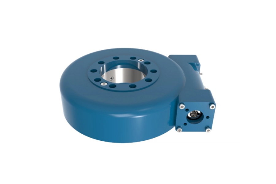
What is a single axis tracker slew drive? It is a compact, sealed rotation unit that combines a slewing bearing, a gear set (worm or spur), a housing and a motor interface. On a horizontal single-axis tracker, it turns the torque tube so the panels follow the sun from east to west.
The wind question is really three questions. Can the gear set hold the tube against aerodynamic torque? Can the bearing carry the tilting moment the structure pushes into it? Can the drive limit free play so the tube does not rock under gusts? A drive can pass one of these checks and fail another, so each needs its own number.

How Wind Reaches the Drive: Three Separate Load Paths
Wind does not load a slew drive in one way. It arrives as torque on the gear mesh, as a tilting moment on the bearing, and as small repeated motion through any free play. Mixing these up is the most common reason a drive looks adequate on paper.
| Load path | Where it acts | What it stresses | Trade-off to watch |
|---|---|---|---|
| Aerodynamic torque about the rotation axis | Gear mesh (worm and wheel, or pinion and ring) | Tooth flanks, worm shaft, motor brake or self-locking | Higher gear ratio improves holding but slows stow movement |
| Overturning (tilting) moment | Slewing bearing raceways and mounting bolts | Rolling elements, raceway contact, flange bolts | A larger bearing raises moment capacity but adds weight and cost |
| Dynamic oscillation through free play | Backlash zone of the gear set | Tooth impact, fatigue, tracking accuracy | Tighter backlash helps stiffness but needs better machining and alignment |
Torque and overturning moment come from the same gust but follow different paths. Torque depends on where the pressure center sits relative to the tube axis. Overturning moment depends on panel area, row height and how the structure is supported.
Parameters That Matter and What They Change in Practice
Datasheet values only help if you know what each one controls. These are the ones I check first when reviewing a tracker drivetrain.
- Holding torque (static). This is what the drive can resist without moving. Conclusion: use it for stow checks, not the running torque rating. It applies when the motor is off and the drive is locked. It does not cover shock loads unless the supplier states so.
- Output torque (running). This is what the drive delivers while tracking. It decides whether the drive can push the array back to stow in a rising wind. A high running torque does not mean a high holding torque.
- Tilting moment capacity of the bearing. This limits how much overturning load the bearing carries together with axial and radial loads. Ask for the static limit curve, not one number, because the allowed moment drops as axial load changes.
- Backlash. It sets how far the tube can move before the gears take load. Less backlash reduces rocking and impact. It cannot cure a structure that is torsionally soft.
- Sealing (IP rating). Wind-driven dust and sand can enter weak seals. Our drives reach IP66 protection in the range, and the US desert-site case below used IP65. Sealing protects the gears; it adds no wind capacity.
Worm gear versus spur gear for wind-heavy sites
| Item | Worm gear drive | Spur gear drive |
|---|---|---|
| Static holding | Can self-lock through friction at suitable lead angles | Usually relies on motor brake or gearmotor holding |
| Efficiency | Lower, so more motor power is needed | Higher, so energy use is lower |
| Best fit | Sites where holding without power matters most | Projects that prioritize efficiency and a lighter drive |
| Limit | Self-locking is not a safety guarantee under vibration | Brake sizing must be verified against stow torque |
Both types are in our range: see the Worm Gear Slew Drive and Spur Gear Slew Drive pages. The right choice depends on your wind table, stow strategy and power budget, not on gear type alone.
Request Your Custom Slew Drive or Bearing Spec
Tell us your load, speed, and environment — receive a tailored 100–5000 mm slewing drive or slewing bearing proposal with 3D drawings within 24 hours.
When Overturning Moment, Backlash and Stow Position Exceed the Usable Torque Margin
Usable torque margin is the gap between what the drive can safely resist and what wind demands, after your safety factors. It shrinks fast in three situations. For a single axis tracker slew drive, each one needs a check before design freeze.
| Condition | Why the margin shrinks | What to check |
|---|---|---|
| High overturning moment combined with axial load | The bearing's allowed moment falls as load combinations rise, and bolt preload can be consumed | Plot the combined load point on the bearing's static limit curve; check bolt grade and preload |
| Backlash larger than the structure's torsional play budget | The tube accelerates through the gap and hits the gear flank, so peak load exceeds the static wind torque | Request measured backlash per unit, and ask how it changes as the gears wear |
| Stow angle that leaves the array catching wind | An unfavorable stow angle raises aerodynamic torque on the gear set. A stow angle that cuts torque lowers it | Get the wind-tunnel or code-based torque at your stow angle, then compare it with static holding torque |
| Stow motion needs power but power is lost | If the array must move to stow under load, running torque and motor supply both become limits | Check whether stow is passive (self-locking, brake) or active (motor-driven) in your control logic |
A simple rule applies here. If factored wind torque at stow exceeds the drive's static holding torque, the drive will back-drive or slip. If the combined moment point sits outside the bearing curve, the drive may hold torque and still damage its raceways.
Limits of this check: it assumes steady, equivalent static loads. Gust factors, torsional galloping and fatigue from daily cycling need a separate dynamic review with your tracker's structural model.
Common Misunderstandings Before You Specify a Drive
- Using running torque as the wind rating. Running torque is for tracking. Stow is a static or dynamic holding case with different limits.
- Treating self-locking as unconditional. Friction-based locking is dependable for steady loads. Sustained vibration or shock can reduce it, so confirm with a brake or test data when wind is severe.
- Judging tilting moment alone. The bearing also sees axial and radial loads, and the combination sets the limit.
- Chasing the lowest backlash. Too little backlash can raise friction and heat in a gear set. The target is controlled backlash that fits your structure's stiffness.
- Comparing ratings from different test conditions. Holding torque measured at different temperatures, safety factors or load definitions is not equal data.
How to Verify the Numbers Before You Commit
- Define the load case. Collect factored wind torque, overturning moment, axial load and radial load at the drive point for operating and stow conditions.
- Request the limit data. Ask for static holding torque, running torque, bearing limit curve and measured backlash, each with test conditions stated.
- Check the stow logic. Confirm the stow angle, whether the drive moves under load, and what holds the array if power fails.
- Review quality evidence. Ask for inspection and load-test records. At Luoyang Slewring Bearing Co., Ltd., every slew bearing passes CMM three-coordinate inspection and dynamic load testing, within an ISO 9001:2015 quality system. See our Slew Drive Quality Control process for details.
- Test a sample. A single standard unit is available (MOQ 1 set) for evaluation. Customized designs start at 5 sets.
These steps establish whether the drive fits your wind case. They do not replace a full structural analysis of your tracker, and they cannot fix a wind table that was assumed rather than measured.
Where This Has Been Applied
Two of our tracker projects show how site conditions shape the choice. For South American solar projects in Brazil, Argentina and Chile, we supplied SP-I 0229 spur gear slew drives for single-axis solar trackers, with an energy yield gain of up to 40% reported for the tracker systems. For a US renewable energy equipment manufacturer, we delivered 50 units of SP-I 0841 for utility-scale tracker systems, specified at IP65 for desert sites.
Those results belong to each project. Your wind table, stow strategy and site dust level may call for a different frame size or sealing grade. You can review the SP-I Slew Drive series as a starting point, or look at the wider Slew Drive range.
Checklist for your technical team
- Factored stow torque and overturning moment, with the code or tunnel study source
- Combined axial, radial and moment load point against the Slewing Bearing limit curve
- Static holding torque and backlash with test conditions
- Sealing level for dust, sand or coastal exposure
- Need for a Customized Slew Drive if standard frames do not fit your mounting or load case
If your project data is ready, send it to our engineers. We provide a technical proposal within 24 hours, a 48-hour technical response, and a 2-year extended quality warranty on supplied units. Standard production runs about 9 days, with 3-day rapid prototyping available for custom work.
Request Your Custom Slew Drive or Bearing Spec
Tell us your load, speed, and environment — receive a tailored 100–5000 mm slewing drive or slewing bearing proposal with 3D drawings within 24 hours.
 WhatsApp

 +8613903880726