



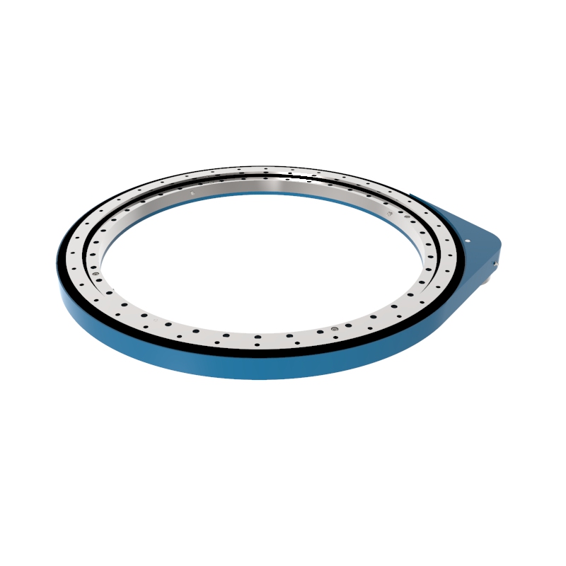
What is a slewing ring? It is a large-diameter slewing bearing that lets one part of a machine rotate against another while carrying axial, radial, and tilting loads. Cranes, excavators, solar trackers, and turntables all depend on one.
When an operator reports wobble or vibration, you need to know which part is moving wrong: the bearing, the mounting structure, or the gear. A slewing ring inspection with a dial indicator can answer that in about an hour, but only if the indicator sits in the right place.
This guide shows the setup, the measuring positions, and the limits of what the readings can tell you. It is written for field technicians and OEM service teams who already have a machine on site and a complaint to resolve.
What You Need Before the First Reading
Most failed measurements fail before the indicator touches the ring. The base moves, the surface is dirty, or nobody knows what number counts as "too much." Sort the list below first.
- Dial indicator and magnetic base. A 0.01 mm (0.0005 in) graduation is typical for this work. Add an extension rod so the base can sit on solid structure, not on a thin cover plate.
- Zero-check surface. A gauge block or a known flat plate. Confirm the indicator returns to the same reading after a few touches.
- Angle marks. Paint marker or tape to mark eight positions, 45° apart, on the rotating ring.
- Torque wrench and the bolt torque record. You will need both to rule out loose fasteners.
- The bearing drawing or data sheet. It gives the allowable runout and clearance for your exact model.
- Lockout and load support. Boom blocked, pressure released, nobody inside the swing radius.
Only two items block progress: safe load support and a stable base position. The allowable limit can be clarified later. You can collect readings now and compare them once the manufacturer's data arrives.
Step-by-Step Dial Indicator Sequence
Follow this order. Each step depends on the one before it, and skipping the baseline step makes every later reading hard to trust.
- Support and clean. Park the machine, lock out the drive, and block any loaded structure. Wipe the measuring surfaces so paint flakes and grease do not move the stylus.
- Mark the ring. Put a zero mark on the rotating ring and a fixed reference mark on the stationary structure. Mark seven more points at 45° steps.
- Mount the base on the stationary side. The base must not ride on the part you are measuring. Shake the stand by hand. If the needle moves, relocate it.
- Measure axial runout. Place the stylus on the flat face of the rotating ring, square to the surface, with about half the stroke preloaded. Zero the dial at position 0.
- Rotate slowly through one full turn. Stop at each mark and record the reading. Move at hand speed or creep speed, not at operating speed.
- Return to zero. The dial should come back to its starting value at position 0. If it does not, the base shifted or the ring moved axially. Discard the run and reset.
- Measure radial runout. Move the stylus to the outside diameter or a machined bore of the rotating ring. Repeat the same eight-point turn.
- Repeat at a second base location, 180° across. Two bases give you a cross-check against a bent bracket or a single bad spot.
- Run a second turn. Readings that repeat within the indicator's resolution are real. Readings that wander are a setup problem.
Checkpoint: two full turns with matching readings at every mark. Until you have that, do not draw conclusions about the bearing.
How Dial-Indicator Setup and Measurement Locations Isolate Runout, Clearance Growth, and Mounting Distortion
A single runout number hides its cause. The same 0.5 mm swing could come from a worn raceway, a warped flange, or a loose bolt group. Where you place the base and stylus, and whether the ring is rotating or loaded, decides which cause the reading points to.
| Fault source | Indicator setup | Where to measure | Signature in the readings |
|---|---|---|---|
| Runout (ring or mating part out of true) | Base on stationary structure, stylus on rotating ring face (axial) or outside diameter (radial) | Eight points through a full turn, no external load change | Smooth sine-shaped swing that repeats every turn and travels with the rotating ring |
| Clearance growth (raceway or rolling-element wear) | Base on the fixed ring or fixed structure, stylus on the rotating ring edge, ring stationary | Four points, 90° apart, with the load reversed by lifting and releasing the boom or platform, or by a controlled jack force | Reading changes between loaded and unloaded states, and the change is larger at the loaded-zone positions than at the opposite side |
| Mounting distortion (flange not flat, bolts uneven) | Base on the rotating side, stylus sweeping the fixed ring face, or indicator on the fixed ring while bolts are re-torqued in sequence | Fixed positions on the stationary structure, plus the bolt-group areas | High and low points stay at the same angle on the structure no matter where the rotating ring stops; readings shift after re-torquing |
| Gear-ring wobble (geared ring) | Stylus on the gear tip or the gear-side face, base on stationary structure | Same eight points, then compare with the raceway-side face reading | Gear-side swing larger than raceway-side swing points to the gear, not the raceway |
The key question is what the pattern follows. If the high spot rotates with the ring, look at the ring, its mounting surface, or the part bolted to it. If the high spot stays fixed in space, look at the support structure under the stationary ring.
For clearance, the tilt test matters more than rotation. Clearance growth shows up when the load direction changes, not when the ring simply turns. A free-spinning ring with a large tilt movement is a typical wear signature on a bearing that "feels fine" by hand.
Where this does not apply: if the structure itself flexes under the test load, the tilt reading will include that flex. Place the base as close to the ring as you can, and note any bracket deflection before you blame the raceway.
Request Your Custom Slew Drive or Bearing Spec
Tell us your load, speed, and environment — receive a tailored 100–5000 mm slewing drive or slewing bearing proposal with 3D drawings within 24 hours.
Reading the Results Without Over-Calling a Fault
A dial reading means little without a limit. Use the allowable runout and clearance on the drawing for your model, and apply them at the same measuring positions the drawing assumes. If you do not have the drawing, send the model plate photo and your readings to the supplier before you condemn the ring.
| Observed pattern | Most likely source | Next action | Limit of this reading |
|---|---|---|---|
| Axial swing repeats each turn, follows the rotating ring | Out-of-flat rotating-side flange or a bent mating part | Check flange flatness and bolt seating on the rotating side | Cannot separate a bad flange from a damaged raceway without a removal check |
| Axial swing stays at fixed angles on the structure | Support-structure distortion | Check structure flatness; re-torque in the specified sequence and re-measure | Weld distortion can look the same as a loose bolt group |
| Tilt reading grows under load reversal | Clearance growth from raceway wear | Compare with baseline or maker's data; plan inspection of raceway and grease for metal particles | Structure flex can add to the number |
| Radial swing large, axial swing small | Eccentric seat or radial-wear pattern | Check the pilot diameter fit and radial support | Out-of-round paint or a rough stylus surface can fake it |
| Gear-side wobble larger than raceway-side | Gear-ring or pinion mesh issue | Inspect backlash and pinion alignment separately | This is a mesh problem, not a raceway verdict |
One rule helps in the field. Do not call a bearing worn from runout alone. Runout points to where to look next, while clearance under load reversal, together with grease condition and torque records, supports the replace-or-repair decision.
Common Setup Mistakes That Fake a Fault
- Base on the rotating part. The reading then measures nothing useful. Always anchor on the stationary side.
- Stylus not square to the face. A tilted stylus adds a cosine error and drifts when you rotate. Check perpendicularity by eye from two sides.
- Measuring on a paint ridge or weld bead. The needle jumps at one mark every turn. Pick a clean, machined surface.
- Skipping the second turn. One turn can hide a shifting base. Two matching turns confirm the data.
- Testing clearance with the structure unsupported. The boom sag then looks like bearing play.
- Re-torquing bolts before measuring. It erases evidence of distortion. Measure first, record, then correct the torque.
Each of these produces a believable number. That is why a documented baseline is worth more than any single reading.
Completion Check, Recovery, and Variations
You are done when you can state three things: the axial and radial runout values with their repeat accuracy, the tilt-movement value under load reversal, and the angle at which any high spot sits relative to the fixed structure. If any of the three is missing, go back to the step that produces it.
If the two turns do not repeat, revisit the base mounting. If the high spot follows the rotating ring, revisit the flange and mating surface. If the tilt movement exceeds the limit for the model, move to a raceway and grease check, then plan the replacement.
Two variations change the procedure. On a geared slewing ring, add the gear-side readings from the table above. On an integrated slew drive, also check the housing and output flange, and inspect the drive for backlash, because the worm-gear mesh can add play that a bare bearing does not have.
Precision-sensitive installations leave little room for mounting error, so a baseline matters. A South Korean port equipment manufacturer reordered 20 WEA9-62-25HR single worm slew drives for port crane systems, built for ≤0.15° tracking precision with IP65 sealing and self-locking. A British Columbia forestry equipment manufacturer ordered 30 WED14-86-25BHR.5 double worm slew drives for grapple machines at ≤0.13° precision. On units like these, readings taken at commissioning give you the reference for every later check.
For heavier platforms, such as the 100 SEA21-125-25HR(2) units a Houston engineering machinery manufacturer uses on slewing platforms, the same eight-point routine works. The main change is the larger structure, so the base placement and structure-flex check matter more.
On our side, every slew bearing at Luoyang Slewring Bearing Co., Ltd. passes CMM three-coordinate inspection and dynamic load testing under our ISO 9001:2015 quality system. You can read more about that process on our slew drive quality control page. If your slewing ring inspection data suggests a confirmed manufacturing defect, our 2-year extended quality warranty and free replacement for confirmed defects apply. Send your readings, model plate, and photos, and our engineers respond within 48 hours.
If the readings point to replacement, we can supply both standard and customized slew drive solutions, with a technical proposal within 24 hours. Standard products start at 1 set, and customized products at 5 sets.
Request Your Custom Slew Drive or Bearing Spec
Tell us your load, speed, and environment — receive a tailored 100–5000 mm slewing drive or slewing bearing proposal with 3D drawings within 24 hours.
 WhatsApp

 +8613903880726