



Why does a mounted joint slip even when the bolts appear tight? The answer usually lies in lost clamp force, not simply in a loose nut or an incorrect wrench setting. Mounting bolt tightening must create and retain enough preload to hold two mating surfaces together under operating load.
For field service teams, the visible symptom may be a shifted witness mark, reddish-brown fretting debris, recurring retightening needs, or movement between a mounting flange and structure. These signs do not prove one cause. They indicate that the joint needs a structured inspection before a bolt is replaced, a torque value is changed, or a slewing component is removed.
This diagnostic process applies to a Slew Drive, a Slewing Bearing, and related mounted rotary equipment. Luoyang Slewring Bearing Co., Ltd. supports standard and customized rotary transmission assemblies, but the joint structure, bolt specification, mounting faces, and operating loads must still be evaluated as one system.
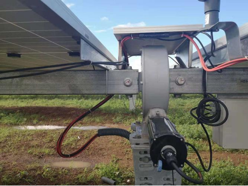
Separate the Visible Symptom from the Actual Cause
Start by describing what changed during operation. Do not begin with the assumption that bolts were under-torqued. A joint can move after correct installation if settling, paint compression, flange distortion, wrong bolt selection, repeated overload, or poor contact reduces the available clamping force.
The first conclusion to reach is simple: determine whether the problem is joint movement, bolt rotation, component damage, or only surface discoloration. Each condition calls for a different next step. A dark stain around a bolt does not automatically mean the bolt has loosened, while a broken paint witness line across two parts is stronger evidence that relative movement has occurred.
| Observed condition | What it may indicate | Next check | Limit of the observation |
|---|---|---|---|
| Witness marks no longer align | Relative movement between the mounted parts | Inspect the full bolt circle and mating-face contact | Does not identify whether movement began from overload, settling, or low preload |
| Reddish or dark powder at the flange | Fretting caused by micro-movement | Check for paint compression, surface damage, and repeat loosening | Powder can appear after an earlier event and may not show when it started |
| One or more bolts turn before expected during checking | Possible preload loss or a damaged thread condition | Review bolt condition, lubrication condition, and tightening sequence | Turning behavior alone does not prove the original assembly torque was wrong |
| Visible gap at part of the flange | Uneven support, distorted structure, foreign material, or damaged mounting face | Stop further loading and assess flatness and contact | A gap may be difficult to see at all locations without access |
| Recurring loosening at the same location | Local contact loss, local load concentration, or structural flexibility | Compare that area with adjacent positions and inspect the support structure | Replacing only that bolt may not correct the source condition |
If the equipment has a visible flange gap, active joint movement, cracked hardware, damaged threads, or abnormal movement that affects safe operation, remove the equipment from service according to the site safety procedure. Continuing to cycle the assembly can enlarge damaged contact areas and make the original cause harder to identify.
Use an Ordered Field Inspection Before Retightening
A useful inspection begins with accessible evidence. Retightening first can hide the condition of the joint and may force a damaged interface back together without correcting the cause. Record the position of affected bolts, the direction of movement, recent work performed, and whether the problem appeared after commissioning, repair, transport, or a load event.
- Review the assembly record. Confirm the applicable drawing, bolt size and grade, specified tightening method, washer arrangement, lubrication instruction, and tightening sequence. Use the component supplier’s documentation rather than a generic automotive torque chart.
- Inspect external evidence. Look for broken witness marks, polished areas, fretting debris, displaced paint, deformation near bolt holes, and leakage or interference that may be related to movement.
- Check the bolt circle in pattern. Compare positions around the full circumference. A local problem points toward local support loss or load concentration; widespread change points more toward settling, procedure error, or a system-level issue.
- Inspect accessible mating areas. Look for coating buildup, burrs, weld spatter, trapped debris, corrosion, or a visible gap. Do not use a fastener to pull a distorted mounting structure flat.
- Verify hardware consistency. Check whether the installed bolts, washers, nuts, and locking method match the approved bill of materials. Mixed hardware can produce uneven preload even when the same wrench setting was used.
- Review operating history. Identify shock loading, impacts, changed attachments, altered duty cycles, or unusual side loads. These can affect the joint even if installation was correct.
This order fits field teams because it preserves evidence and avoids unnecessary removal. It does not replace a manufacturer’s assembly procedure. If the drawing specifies a particular staged pattern, lubrication condition, or recheck instruction, that document controls the work.
For high-load mounting arrangements, the support structure matters as much as the fastener. This is especially true for a Heavy load slewing bearing, where load distribution through the ring and mounting faces should be assessed alongside the bolt condition.
When Apparent Torque Is Not Enough for Settling, Paint Compression, or Uneven Contact
Apparent torque can be misleading because torque is only an indirect indicator of clamp force. A wrench may reach the specified setting while the joint continues to settle afterward. When coatings compress, contact points flatten, or the mounting faces touch unevenly, bolt stretch and usable preload can fall even though the recorded tightening value looked correct.
The practical conclusion is not to increase torque without review. First determine whether the joint lost clamp force after assembly or whether the interface never had full support. Increasing the setting without addressing the contact condition can damage threads, overload bolts, or distort the mounted component.
| Boundary condition | Observable judgment criteria | Likely effect on clamp force | Recommended next action | When this explanation does not fit |
|---|---|---|---|---|
| Settling after assembly | Fasteners were installed recently; witness marks remain mostly aligned; subsequent checks show changed bolt condition across much of the circle | Surface asperities, washers, and interfaces may settle, reducing preload | Follow the approved recheck procedure and inspect for uniform contact | Less likely when only one area shows movement or a local gap is present |
| Paint or coating compression | Coating is present between structural mounting faces; compressed or crushed coating appears near bolt locations | Coating thickness reduces as load is applied, allowing preload loss | Review whether the drawing permits coating in the clamped interface; assess the full face condition | Does not explain movement where clean metal-to-metal contact is confirmed and support is uniform |
| Uneven contact | Polished high spots, localized fretting, visible gaps, debris, burrs, or unequal marks around the flange | Some bolts support more load while other areas receive little clamp force | Inspect flatness, support stiffness, and contamination before reassembly | Not confirmed merely because one bolt has loosened; check structural loading too |
| Local structural flexibility | Movement repeats near brackets, cutouts, weld transitions, or highly loaded attachment points | Deflection can unload selected bolts during service | Assess the mounting structure and actual load path with engineering support | Less likely if movement is evenly distributed around the full circle |
Use the following diagnosis order. Check for a visible gap or debris first because these conditions can prevent full contact from the start. Next, compare evidence around the bolt circle; uniform signs suggest overall settling, while concentrated signs suggest local contact or structure problems. Then compare the assembly record with the approved procedure before any retightening decision.
Stop and escalate when the mounting face is visibly distorted, the joint has fretted over a broad area, bolt holes appear damaged, or the cause cannot be distinguished from the available evidence. Send photographs of the full bolt circle and affected areas, the product model, mounting drawing, bolt details, tightening record, duty cycle, and a description of when the symptom began.
Request Your Custom Slew Drive or Bearing Spec
Tell us your load, speed, and environment — receive a tailored 100–5000 mm slewing drive or slewing bearing proposal with 3D drawings within 24 hours.
Correct the Cause Instead of Repeating the Same Retightening Cycle
Once the evidence points to a plausible cause, match the action to that cause. Repeatedly applying the same wrench setting is appropriate only when the approved procedure calls for it and the mating surfaces are confirmed acceptable. It is not a cure for structural distortion, incorrect hardware, contamination, or an unsupported mounting surface.
- If settling is the leading cause: use the approved staged tightening and recheck procedure from the product drawing. This fits new or recently serviced joints with broadly uniform evidence. Do not treat it as a solution if one section alone is slipping.
- If paint compression is found: verify the required mounting-face preparation with the equipment designer or component supplier. This fits interfaces where coating is visibly being crushed. Do not remove coating or modify a corrosion-protection system without engineering approval.
- If contact is uneven: correct the support condition before final assembly. This fits joints with debris, burrs, high spots, distortion, or local gaps. Do not use bolts to force large misalignment into place.
- If hardware does not match the approved specification: replace it with approved hardware and inspect threads before assembly. This fits mixed fasteners, incorrect washers, or unapproved locking arrangements. Do not assume a visually similar bolt has equivalent performance.
- If duty loads changed: request an engineering review of the application. This fits equipment with added attachments, impact events, changed cycle frequency, or altered load direction. Retightening alone cannot validate a changed load case.
After corrective work, verify the original symptom rather than relying only on the tightening record. Apply witness marks where permitted by the site procedure, observe whether the marks remain aligned during the defined operating check, and inspect for renewed fretting or a visible gap. If the symptom returns, treat the original diagnosis as incomplete and examine the mounting structure and operating loads again.
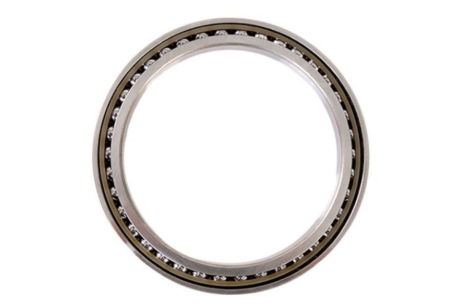
Prevent Repeat Problems Through Controlled Assembly Records
A complete assembly record helps distinguish an installation issue from a later operating issue. For each mounted rotary unit, keep the product model, serial identification if available, drawing revision, bolt specification, hardware source, surface preparation condition, tightening method, sequence, date, and inspection observations.
The most useful records are specific. “Bolts checked” is weak evidence. “Full bolt circle inspected, no visible gap, approved hardware installed, witness marks applied, and condition checked after the defined operating period” gives the next technician something actionable.
| Record item | Why it helps diagnose future slip | Best use case |
|---|---|---|
| Photographs before and after installation | Shows coating condition, witness marks, support geometry, and local interference | Service work, warranty reviews, and repeat equipment builds |
| Approved bolt and washer details | Confirms that hardware was not mixed or substituted | Multi-site assembly and distributor-managed inventory |
| Tightening sequence and tool record | Supports review of assembly consistency | New installation and field repair |
| Operating event history | Links slip symptoms to impacts, overload events, or changed applications | Equipment used in variable or demanding duty cycles |
| Periodic inspection findings | Shows whether the condition is stable, progressing, or localized | Critical rotary joints and recurring service cases |
For customized equipment, involve the rotary component supplier early. A Customized Slew Drive may require a mounting review that considers structural stiffness, gear orientation, load direction, access for service, and environmental exposure. Material selection and protection level should also fit the actual environment rather than the appearance of the machine alone.
Know When Product Support and Quality Review Are Needed
Escalate the case when visible movement continues after verified corrective assembly, when the mounting structure may be damaged, when the bolt circle cannot be inspected safely, or when the correct installation specification is unavailable. A supplier can assess the evidence, but a field report should not claim a manufacturing defect before the mounting interface and operating conditions are reviewed.
Luoyang Slewring Bearing Co., Ltd. operates an ISO 9001:2015 certified quality management system and provides a 48-hour technical response. Our facility uses CMM three-coordinate inspection and dynamic load testing for slewing bearing quality control. Those controls verify the supplied component, but they do not remove the need for proper support structure preparation and correct joint assembly in the field.
For confirmed manufacturing defects, the company provides free replacement under its stated quality terms and offers a 2-year extended quality warranty. To support a fast technical review, provide the component model, installation photographs, bolt and washer details, mounting drawing, service history, recorded symptoms, and clear photos of any fretting or movement marks.
Real application conditions vary. For example, Luoyang Slewring Bearing Co., Ltd. supplied WEA9-62-25HR single worm slew drives for a South Korean port equipment manufacturer’s port crane systems, with IP65 sealing and self-locking performance. That case supports the use of the specified drive in that application; it does not replace a mounting-joint inspection for a different machine, structure, or duty cycle.
The best prevention method is methodical: inspect the interface, verify approved hardware and procedure, correct contact problems before loading the joint, and preserve records for later review. This approach turns recurring loose-fastener reports into evidence-based maintenance decisions instead of repeated wrench work.
Request Your Custom Slew Drive or Bearing Spec
Tell us your load, speed, and environment — receive a tailored 100–5000 mm slewing drive or slewing bearing proposal with 3D drawings within 24 hours.
 WhatsApp

 +8613903880726