



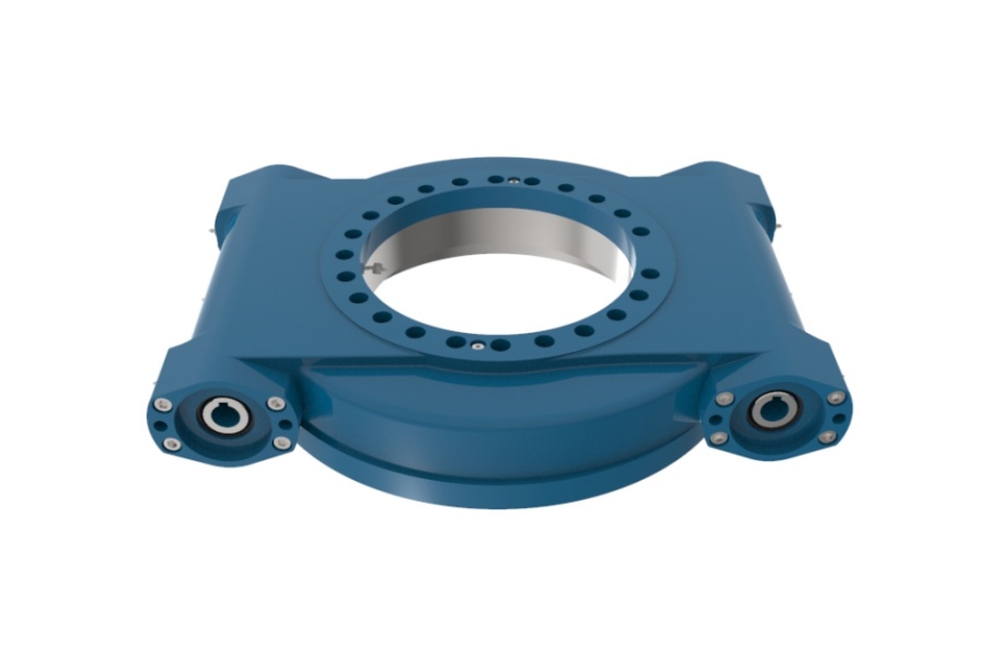
What is a slew drive? A slew drive is a compact rotation unit that combines a slewing bearing, a gear (worm or spur), a housing and a motor interface. It carries axial load, radial load and tilting moment while it turns the load.
So why do drives that passed a paper check still fail in the field? In most cases, the loads were checked one at a time, but they act together. This slew drive selection guide shows you how to build one combined load case, test it against a drive's ratings, and confirm the result before you release a drawing.
What You Need Before You Start
You do not need a finished design. You do need the inputs below. Some block progress and some can be estimated early and refined later.
| Input | Why it matters | Blocks sizing? |
|---|---|---|
| Payload weight and its center of gravity offset from the rotation axis | Sets axial load and the eccentric tilting moment | Yes |
| Structure weight and its center of gravity | Adds to axial load and moment | Yes |
| Wind area, drag assumption, and height above the bearing | Creates a horizontal force, a moment and sometimes a rotating torque | Yes, for outdoor use |
| Speed, acceleration and braking time | Gives inertial torque and extra tilting during start-stop | Yes |
| Shock or snap-load events (hook release, impact, boom bounce) | Raises the peak load above the static value | Can be estimated first |
| Duty cycle, environment, mounting angle | Affects service life, sealing and corrosion needs | Can be refined later |
Tools are simple. You need a spreadsheet, the drive's load chart and the design standard your industry uses for dynamic factors. We do not prescribe a factor here, because crane, solar, marine and platform standards differ.
Why Checking Loads One at a Time Causes Undersizing
A slew drive does not feel loads as separate items. The bearing raceway and the gear mesh see the sum of them at the same moment. A drive that clears each single check can still sit outside its capacity once the loads are added.
The table below shows where the separate-check habit goes wrong, and what the combined method does instead.
| Load source | What a separate check sees | What happens when combined | Combined method |
|---|---|---|---|
| Payload weight | Axial load only | Offset turns weight into tilting moment | Moment = weight × offset, added to the moment total |
| Wind | Small side force | Force at height creates moment that adds to the payload moment | Moment = wind force × height above bearing; add with the same sign as the worst payload direction |
| Acceleration or braking | Torque for rotation only | Inertial force at the payload radius also loads the bearing and the gear teeth | Add inertial torque to wind torque and friction; check the gear and the moment together |
| Shock | Ignored, or a flat safety factor on everything | Peak lands on top of the eccentric load, not the nominal load | Apply the dynamic factor to the load that actually shocks, then add the rest |
| Eccentric payload shift | Checked at center position | Worst position is at the far reach | Run the case at maximum offset |
The common outcome is a drive that looks 30% under capacity on each check, then runs past its tilting moment limit in the real case. The fix is not a bigger safety factor. The fix is a worst-case load point built from all sources at once.
Step-by-Step Load Combination Workflow
Follow these steps in order. Each step feeds the next one.
- Fix the coordinate system. Pick one axis for axial load, one for radial load, and one for tilting moment. Success looks like every load carrying a sign. Most errors start when wind and payload are signed differently.
- List the operating states. Typical states are lifting at full reach, slewing, braking, parked in wind, and a shock event. Write each one as its own row.
- Convert every load to the bearing center. Move each force to the bearing plane. This gives axial load (Fa), radial load (Fr) and moment (M) for each source.
- Apply dynamic factors to the right source. Use your standard's factor on the load that causes the event. Do not multiply wind or structure weight just because the payload shocks.
- Add the sources within each state. Add the signed values for Fa, Fr and M. Then add the rotating torque: wind torque, inertial torque and friction.
- Find the governing state. It is not always the heaviest lift. A parked state in strong wind can govern the moment, while braking at the end of a swing can govern torque.
- Plot the point on the load chart. Check the pair (Fa, M) against the drive's tilting curve. Check torque against the output torque and holding torque ratings.
- Check life, not only peak. If the duty is cyclic, compare the combined load spectrum with the expected service life, not only the single worst point.
For start-stop work, run step 5 twice: once at acceleration and once at braking. Braking often adds torque in the same direction as wind, so it can be the worst case even when the lift is light.
Request Your Custom Slew Drive or Bearing Spec
Tell us your load, speed, and environment — receive a tailored 100–5000 mm slewing drive or slewing bearing proposal with 3D drawings within 24 hours.
Worked Example: Eccentric Payload With Wind and Shock
The numbers below are round figures for illustration only. They are not product ratings. Use your own data and the load chart of the drive you plan to buy.
Assume a rotating platform with a 20 kN payload at 1.2 m offset, an 8 kN structure at 0.2 m offset, and a 3 kN wind force acting 2.5 m above the bearing. Assume a dynamic factor of 1.25 on the payload only.
| Check method | Axial load | Tilting moment |
|---|---|---|
| Payload only, static | 20 kN | 24 kN·m |
| All sources, static | 28 kN | 33.1 kN·m |
| All sources, payload shock factor applied | 33 kN | 39.1 kN·m |
The moment from the payload-only check is 24 kN·m. The combined case is 39.1 kN·m, about 63% higher. A drive sized to the first number would be undersized by a wide margin.
Now add torque. Suppose wind torque is 2.4 kN·m, inertial torque at braking is 4 kN·m and friction is 1.5 kN·m. Added in the same direction, the drive needs 7.9 kN·m, not the 4 kN·m the braking check alone would suggest.
Completion Check and Recovery
You are done when each operating state has one row with signed Fa, Fr, M and torque, and the governing point sits inside the drive's published limits with margin. Margin should come from your standard, not from guesswork.
- Moment point is outside the chart: go back to step 3. The offset or wind height is usually wrong, or the load center was measured from the wrong plane.
- Torque is higher than the rating: go back to step 5. Check that braking torque and wind torque were added, and that the gear ratio and motor output match.
- Calculation passes, but a similar machine shows backlash or noise early: go back to step 4 and step 8. Peak factors or the duty cycle were probably too light.
- The result moves a lot when one input changes: that input blocks progress. Measure it rather than estimating.
Common mistakes we see in load cases:
- Using the payload center instead of the maximum reach position.
- Applying one flat safety factor to every load, which hides the real governing case.
- Ignoring wind on a parked machine because it is not "working."
- Checking Fa and M separately instead of as a pair on the load chart.
- Skipping braking torque because the motor ramps down "slowly."
Variations That Change the Procedure
The workflow stays the same. The governing load and the gear type change with the application.
Single-axis solar trackers
Wind drives the case. Moment and torque from wind dominate, and the drive often holds position for long periods. Our Spur Gear Slew Drive range includes the SP-I series, which was supplied as SP-I 0841 (50 units) to a US renewable energy equipment manufacturer for utility-scale trackers with IP65 sealing for desert sites. SP-I 0229 units were also supplied for solar projects in Brazil, Argentina and Chile.
Cranes on ships, ports and trucks
Shock and braking govern, and holding under wind matters when the crane is parked. A Worm Gear Slew Drive offers self-locking, which helps with holding. A South Korean port equipment manufacturer placed a 20-unit repeat order of WEA9-62-25HR single worm drives for port cranes, specified at ≤0.15° tracking precision with IP65 sealing and self-locking. For truck-mounted use, see our Truck Crane Slewing Drive page.
Heavy-duty steering and mining equipment
Higher torque and shock favor a Double Worm Slew Drive. A Houston, Texas manufacturer ordered 150 units of WED17-104-25HR for heavy-duty wheel steering, and an Australian manufacturer uses HWE21-94-25HR.1 double worm drives in mining excavators.
Turntables and slewing platforms
Eccentric payload and indexing accuracy lead the load case. A Houston, Texas engineering machinery manufacturer ordered 100 units of SEA21-125-25HR(2) for slewing platforms, and a Manchester, UK automation equipment manufacturer ordered 100 units of SP-I 0841-32.1 for automated turntables.

Send Us Your Load Case for a Second Check
You can use the table in the first section as your RFQ list. Send the operating states, signed loads, wind assumptions and duty cycle. Our engineers return a technical proposal within 24 hours, and technical questions get a response within 48 hours.
If standard sizes do not fit the load point, a Customized Slew Drive may be the better route. Standard products start at a 1-set MOQ, and customized products start at 5 sets. Sample orders are welcome for testing.
Our production runs under an ISO 9001:2015 quality system. Every slew bearing is checked on a CMM three-coordinate machine and tested under dynamic load, as described on our Slew Drive Quality Control page. A 2-year extended quality warranty applies, and confirmed manufacturing defects are replaced free of charge.
Start with your own combined load case, then compare it with our Slew Drive and Slewing Bearing ranges. When the governing point sits clearly inside the load chart, the sizing step is complete.
Request Your Custom Slew Drive or Bearing Spec
Tell us your load, speed, and environment — receive a tailored 100–5000 mm slewing drive or slewing bearing proposal with 3D drawings within 24 hours.
 WhatsApp

 +8613903880726