



What is a slew drive? It is a rotary transmission unit that combines a bearing, gear system, housing, and drive input to rotate and support an applied load.
The main question for OEM engineers is not whether a high slew drive reduction ratio produces more output torque. It does. The harder question is whether that extra multiplication leaves enough output speed, acceleration, and response time for the machine to complete its required motion cycle.
This decision affects automation turntables, tracking equipment, crane systems, mobile machinery, and positioning platforms. A drive that holds a load well but cannot complete a repositioning move within the available cycle window can limit the whole machine.
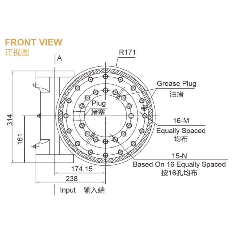
Start With the Motion Requirement Rather Than the Torque Requirement
A reduction ratio describes how many input revolutions are needed to produce one output revolution. As the ratio increases, output torque rises while output speed falls, assuming the same motor input speed and operating conditions.
Higher torque is useful when the application has a large overturning moment, high static resistance, or a need to hold position without continuous braking. However, the drive ratio should follow the total motion duty, not only the highest calculated torque point.
For a first evaluation, define the motion in terms the controls and operations teams can use. Ask how far the machine must rotate, how often it must move, how quickly it must settle, and whether the load must remain fixed when motor power is removed.
| Design Input | What to Confirm | Decision It Affects | Limit of the Check |
|---|---|---|---|
| Required rotation angle | Minimum and maximum travel for each commanded move | Required output speed and available move time | Does not establish load torque by itself |
| Allowed move time | Time from command to stable final position | Whether a higher ratio can meet the cycle target | Must include acceleration and settling time |
| Load condition | Static load, dynamic load, moment load, and resistance during motion | Required output torque and bearing selection | Loads can change across the rotation path |
| Holding requirement | Whether the system must resist reverse motion with power off | Need for self-locking behavior or an added brake | Must be assessed with the full machine load case |
| Operating frequency | How often the machine starts, stops, and reverses | Motor thermal loading and duty-cycle suitability | Requires motor and control data for final confirmation |
The practical conclusion is simple: calculate torque and time together. A ratio selected only from static torque can create a design that is mechanically safe but operationally slow.
This is especially relevant for equipment that alternates between short moves and dwell periods. An automated turntable may have enough time for one long rotation, yet still miss production targets if frequent small-angle corrections take too long to accelerate, settle, and confirm position.
The Operating Boundary Where a High Ratio Harms Cycle Time, Response, or Positioning Throughput Despite Delivering More Torque
A high ratio becomes restrictive when the output speed available from the motor is lower than the speed needed to finish the commanded movement within the allowed cycle time. The exact boundary differs by machine, because it depends on motor speed, load inertia, travel angle, acceleration demand, control behavior, and required positioning accuracy.
The basic relationship is direct. Output speed equals motor speed divided by reduction ratio, so increasing the ratio reduces output speed unless motor speed rises by the same proportion.
Motor speed cannot always be raised to compensate. The motor may reach its speed limit, lose useful torque at higher speed, create excessive heat over repeated cycles, or exceed the practical input conditions of the selected drive. These are design checks, not reasons to assume that a lower ratio is always better.
| Operating Condition | What a Higher Ratio Helps | Where It Can Hurt | Best-Fit Response |
|---|---|---|---|
| Slow solar tracking movement | More torque multiplication and controlled low-speed motion | Usually limited impact if movement is gradual and infrequent | Prioritize holding behavior, environmental sealing, and load capacity |
| Frequent indexing on an automation table | Higher torque margin against rotating resistance | Longer moves, slower correction, and lower parts-per-cycle throughput | Set the required index time before selecting the ratio |
| Heavy crane rotation | Better torque multiplication under load and useful holding characteristics | Slow repositioning if operator response requires faster movement | Evaluate torque, safe speed, and control feel as one system |
| Precision inspection platform | Fine motor-side resolution may improve command granularity | Slow reversal response and longer settling can reduce inspection output | Check actual settle time, backlash effects, and controller tuning |
| High-inertia mobile equipment | More output torque for acceleration and resistance | Motor may work harder during repeated starts and stops | Review duty cycle, thermal behavior, and load inertia with the supplier |
The operating boundary is not a single ratio number. It is the point where the torque benefit no longer offsets lost output speed, slower reversals, or reduced machine throughput.
For example, a positioning unit that moves only a few times per day may accept a slower output speed if holding stability is the top concern. A packaging or assembly machine that indexes repeatedly may need a lower ratio, a different motor arrangement, or a drive configuration designed around faster response.
Self-locking is also not a substitute for a full safety review. If the application has people, suspended loads, stored energy, shock loading, or a defined fail-safe requirement, the machine designer should assess braking and safety functions at the system level.
Separate Observed Application Needs From Assumptions About Ratio Selection
Many product discussions focus on torque multiplication, compact installation, and self-locking characteristics. Those are valid advantages of worm-based designs, but they do not prove that the highest available ratio is suitable for every application.
What can be observed from the supplied application cases is that slew drives serve very different motion duties. Luoyang Slewring Bearing Co., Ltd. supplied SP-I 0229 spur gear slew drives for single-axis solar tracker projects in Brazil, Argentina, and Chile, where the reported project result was energy yield improvement of up to 40%.
That solar project result should not be treated as a general performance promise for every tracker. It is a case-specific outcome, and energy yield can also be influenced by tracker structure, site conditions, controls, layout, and operating strategy.
Other supplied cases show different design priorities. A South Korean port equipment manufacturer placed a repeat order for WEA9-62-25HR single worm slew drives used in port crane systems, with stated tracking precision of no more than 0.15 degrees, IP65 sealing, and self-locking behavior.
Those two applications should not use the same selection logic. Solar tracking normally favors slow, planned movement, while crane positioning may require a balance among load holding, operator response, and controlled rotation under changing load conditions.
- Observation: Worm and spur gear drive formats appear in different supplied projects because application demands differ.
- Interpretation: Ratio selection should start with operating duty, not with a preference for a gear type alone.
- Alternative explanation: A slow machine may be caused by a motor limit, control tuning, excessive inertia, friction, or a poorly defined dwell period rather than the ratio alone.
- Buyer implication: Request an evaluation using the actual load profile, motion angle, cycle target, and motor data.
Luoyang Slewring Bearing Co., Ltd. provides technical proposals within 24 hours, which can help OEM teams compare ratio options early in a project. A useful proposal should state the assumptions used, because an answer based on incomplete load or cycle data cannot replace detailed sizing.
For systems that require a worm configuration, review the available Worm Gear Slew Drive options alongside the required output speed. The correct choice is the one that meets torque and time requirements without forcing the motor or controls outside their intended operating range.
Request Your Custom Slew Drive or Bearing Spec
Tell us your load, speed, and environment — receive a tailored 100–5000 mm slewing drive or slewing bearing proposal with 3D drawings within 24 hours.
Use a Ratio Selection Procedure That Tests Torque, Time, and Duty Cycle
A structured procedure prevents a familiar mistake: approving a high-ratio drive because it meets peak torque, then discovering later that the machine cannot meet its production cycle. The following sequence is suitable for early OEM evaluation before final calculations and validation.
- Define the output motion. List the rotation angle, required move time, dwell time, direction changes, and acceptable final-position settling behavior.
- Identify the worst load cases. Include static load, dynamic load, moment load, friction, external resistance, and any load changes over the travel path.
- Set the required holding behavior. Confirm whether the drive must resist reverse movement with motor power removed, or whether the machine will use an external brake.
- Check motor capability. Review motor speed range, available torque across that range, thermal limits, acceleration demand, and controller behavior.
- Compare ratio candidates. For each candidate, calculate output speed, available output torque, estimated acceleration capability, and total time to move and settle.
- Review repeated operation. Test the expected start-stop frequency, reversals, and heat buildup over the real duty cycle rather than one isolated move.
- Validate the interface. Confirm mounting structure, load path, gear input, environmental protection, lubrication approach, and inspection requirements.
The conclusion from this process is not automatically “choose the lower ratio.” A higher ratio remains appropriate when torque, holding, and low-speed control matter more than rapid rotation, such as a slow tracker or a heavily loaded holding application.
It does not apply as a shortcut for final safety approval. Final selection should include detailed load calculations, motor data, structural checks, and application-specific verification.
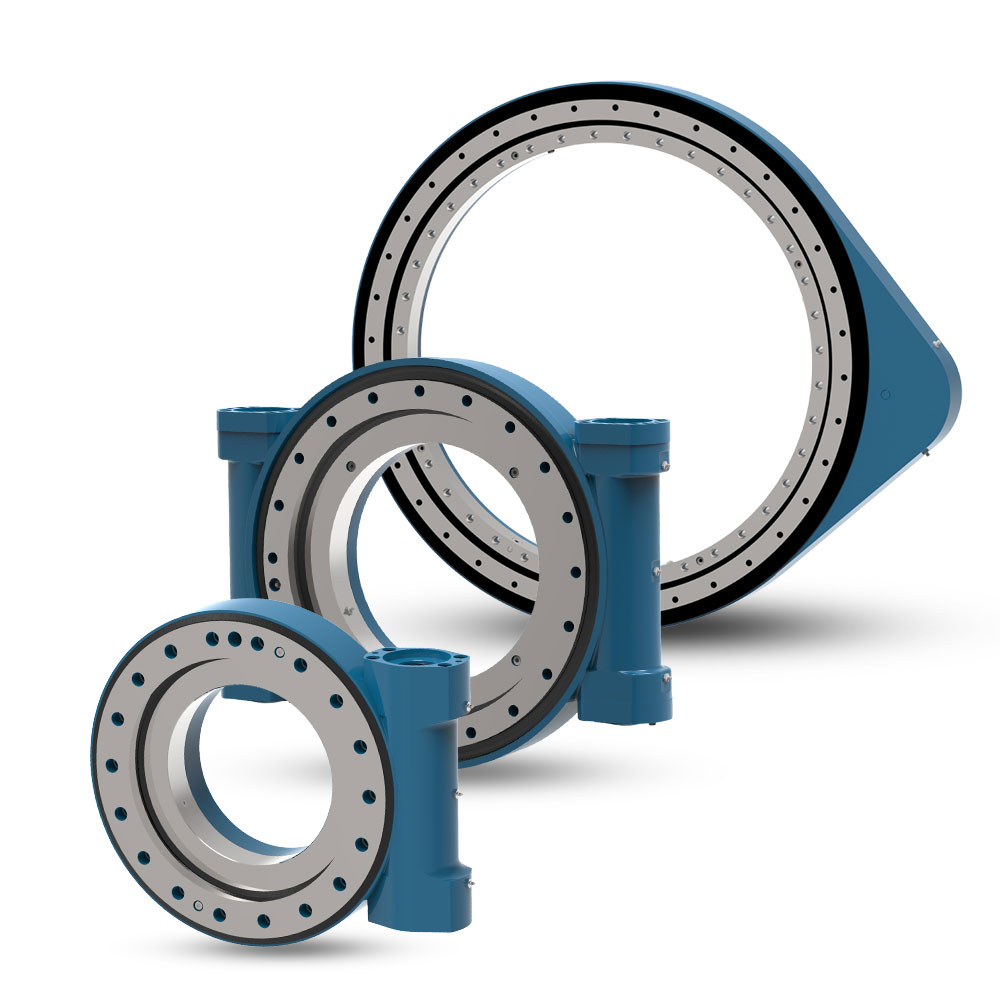
Common Ratio Selection Mistakes That Reduce Machine Throughput
The most expensive ratio errors often appear after controls integration, when changing a drive can affect mounting, motor selection, wiring, software limits, and production schedules. Catching them at the concept stage is less disruptive.
- Selecting from peak torque only. This fits slow, heavily loaded holding duties, but it does not fit a fast indexing system unless move time is checked at the same time.
- Using no-load rotation time. A drive can look fast during a light test yet respond much differently with real inertia, friction, and external load. Use the actual operating load case.
- Ignoring acceleration and deceleration. Constant-speed travel is only part of the cycle. This matters most for short index moves, where ramping and settling may take more time than steady rotation.
- Assuming more reduction always improves accuracy. A higher ratio can improve motor-side command resolution, but final positioning also depends on backlash, structural stiffness, load disturbance, encoder feedback, and controller tuning.
- Assuming self-locking removes all brake needs. This may fit certain holding applications, but it does not replace a system-level safety analysis for people-facing or high-consequence machinery.
- Skipping environmental requirements. A ratio is not the only purchase criterion. Dust, moisture, corrosion exposure, and temperature conditions can determine housing, seal, and material requirements.
Environmental conditions are especially relevant for outdoor equipment. Luoyang Slewring Bearing Co., Ltd. offers slew drives with protection up to IP66 and anti-corrosion performance up to C4H, subject to the selected configuration and operating requirement.
For equipment with repeated reversing loads or demanding stability requirements, a Double Worm Slew Drive may be worth evaluating. It should be selected for the actual load and precision need, not simply because it is a more complex arrangement.
Match the Drive Type to the Machine’s Real Operating Pattern
Worm, double worm, and spur gear configurations can each be suitable depending on torque demand, holding needs, movement frequency, and allowable repositioning time. The correct product choice comes after the motion duty is defined.
For slow tracking systems, a spur gear option may suit the duty when self-locking is not the primary requirement. Luoyang Slewring Bearing Co., Ltd. supplied fifty SP-I 0841 units to a U.S. renewable energy equipment manufacturer for utility-scale solar tracker systems, with IP65 specified for desert sites.
For high-load machinery with reverse loads, drive arrangement and stiffness may matter more than the fastest possible movement. An Australian heavy equipment manufacturer used HWE21-94-25HR.1 double worm slew drives for mining excavators, while a British Columbia forestry equipment manufacturer used WED14-86-25BHR.5 double worm slew drives for forestry grapple machines with stated precision of no more than 0.13 degrees.
These examples show application scope, not a universal recommendation. Mining excavators, forestry grapples, solar trackers, and automated tables have different load paths, duty cycles, environmental exposure, and control targets.
| Machine Priority | Ratio Direction to Evaluate First | Why | When That Direction May Not Apply |
|---|---|---|---|
| High holding torque with slow scheduled movement | Higher ratio | Torque multiplication and low-speed control may outweigh output-speed loss | Not suitable if recovery moves or emergency repositioning must be fast |
| Frequent indexing and high throughput | Moderate or lower ratio | More output speed may support shorter move cycles | Not suitable if torque margin becomes inadequate under the real load |
| Heavy reversing loads | Evaluate drive arrangement before ratio alone | Load stability, structure, and gear engagement may control the choice | Does not remove the need to confirm output speed and duty cycle |
| Outdoor tracking equipment | Ratio based on wind load and tracking schedule | Slow motion can be acceptable when holding and environmental protection are priorities | Site-specific structural and control requirements still apply |
For unusual mounting, torque, speed, or environmental requirements, a Customized Slew Drive can be evaluated after the operating boundary is defined. Standard products can be ordered from one set, while customized products have a minimum order quantity of five sets.
Questions to Send With an Early Supplier Inquiry
A supplier can give a more useful answer when the request includes measurable operating information. This short checklist helps purchasing teams, project managers, and engineers avoid receiving a quotation that only addresses physical size or rated load.
- What is the required rotation angle for each move?
- What is the maximum allowed time from motion command to stable final position?
- How many starts, stops, and reversals occur during the expected duty cycle?
- What are the static, dynamic, axial, radial, and overturning loads?
- Does the load create different resistance at different rotational positions?
- What motor type, speed range, control method, and brake arrangement are planned?
- Must the drive hold position without motor power?
- What precision or tracking requirement must be met at the output?
- What dust, water, corrosion, and temperature conditions will the unit face?
- What mounting envelope and interface constraints cannot change?
Luoyang Slewring Bearing Co., Ltd. operates an ISO 9001:2015-certified facility with six production lines and an annual capacity of 100,000 sets. For quality verification, every slewing bearing passes CMM three-coordinate inspection and dynamic load testing under the company’s stated quality-control process.
Buyers can also review the company’s Slew Drive Quality Control approach when inspection evidence and traceability are part of supplier approval. The company provides a two-year extended quality warranty, a 48-hour technical response, and free replacement for confirmed manufacturing defects.
The right reduction choice is the ratio that meets the load requirement without sacrificing the machine’s required motion schedule. When torque, output speed, acceleration, settling, motor limits, and duty cycle are checked together, the selected Slew Drive is more likely to support both mechanical reliability and usable machine throughput.
Request Your Custom Slew Drive or Bearing Spec
Tell us your load, speed, and environment — receive a tailored 100–5000 mm slewing drive or slewing bearing proposal with 3D drawings within 24 hours.
 WhatsApp

 +8613903880726