



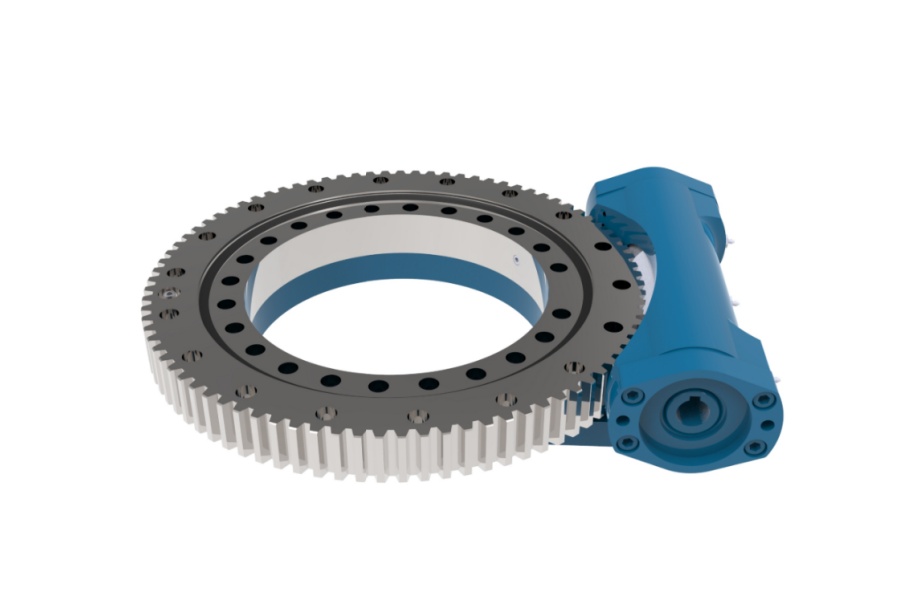
What is a slew drive? A slew drive is a compact rotary transmission unit that combines a slewing bearing, gear set, housing, and drive input to rotate loads such as solar trackers, cranes, turntables, aerial platforms, and handling equipment.
When equipment begins to show extra rotational movement, maintenance teams often describe the symptom as increasing slew drive backlash. That description is useful, but it does not identify the failed part. The apparent free movement may come from the worm-and-gear mesh, the bearing raceway, loose mounting bolts, a moving support structure, shaft movement, or several of these conditions at the same time.
The goal of diagnosis is not to find any movement and immediately order a replacement drive. The goal is to isolate where the movement occurs, determine whether it is stable or growing, and decide whether adjustment, mounting repair, structural work, engineering review, or replacement is the appropriate next step.
Start by Separating the Symptom From the Actual Fault
Rotational play is an observation. A fault is the physical reason the movement exists. Operators may first notice a delayed response when reversing direction, unstable positioning, gear noise, uneven tracking, or a platform that moves slightly after the motor stops.
Begin with a short operating record before touching adjustment points or removing guards. Compare the current behavior with recent operating history, including load changes, impacts, unusual noise, lubrication work, motor replacement, mounting work, and control-system changes. This helps prevent a recent external change from being mistaken for internal drive wear.
Record the operating condition before disassembly
- Direction reversal: Observe whether the delay occurs in both directions or mainly in one direction. One-sided behavior may point toward localized tooth wear, damaged tooth contact, or uneven loading.
- Position dependence: Move the equipment through several positions. If movement changes significantly at different rotational positions, inspect for localized gear wear, tooth runout, raceway damage, or mounting distortion.
- Load dependence: Compare unloaded and normal-duty conditions where safe. Movement that rises only under working load can indicate structural flexing, loose mounting, bearing play, or torsional deflection rather than gear clearance alone.
- Noise and feel: Listen for clicking, knocking, grinding, or a repeated tight spot. A smooth free movement suggests a different branch of diagnosis than rough movement or a hard bind.
- Visible movement location: Watch the housing, mounting interface, output flange, and driven structure while another trained person performs a controlled reversal. The location of visible movement is often more useful than the total amount seen at the outer load.
Do not rely only on a movement reading taken at the end of a long boom, panel row, or platform. A long structure can magnify small motion at the drive. It can also flex independently, making the drive appear worse than it is.
For equipment using a Worm Gear Slew Drive, direction reversal is especially useful because the worm mesh, bearing support, mounting arrangement, and driven structure can be observed while torque changes from one direction to the other.
Use a Fault-Isolation Order Before Adjusting or Replacing Parts
The fastest repair is not always the first repair attempted. Start with external and accessible checks, then move toward internal components only when the evidence supports that step. This order reduces the risk of changing gear settings when the real problem is a loose bolt group or flexible support frame.
- Confirm the symptom under controlled conditions. Secure the work area, remove load only when the machine procedure allows it, and repeat the same reversal movement several times. Record whether the symptom is repeatable.
- Inspect mounting interfaces first. Look for loose fasteners, damaged washers, fretting marks, paint crushing, shifted witness marks, cracked supports, or gaps between the drive and its mounting surface.
- Observe the housing and driven flange. During a controlled reversal, identify whether the housing moves relative to the machine frame, whether the output flange moves relative to the housing, or whether the structure twists beyond the drive.
- Check input-side movement. With power isolated according to site procedure, inspect couplings, motor mounts, gearbox adapters, and worm-shaft support for abnormal visible motion or looseness.
- Assess gear-mesh behavior. Rotate through several positions and note whether resistance, noise, or free movement changes. Variation around the rotation is a useful clue that the condition is not uniform.
- Assess bearing-related movement. Check for rocking, axial shift, or radial movement at the output interface as permitted by the equipment procedure. Bearing play should be evaluated separately from gear clearance.
- Escalate before internal adjustment. If the fault source remains uncertain, stop before changing preload, shimming, or tooth contact settings. Incorrect adjustment can cause binding, heat, accelerated wear, or loss of expected service life.
A practical rule applies: if visible movement occurs between the housing and machine frame, the mounting system must be addressed before diagnosing internal gear wear. If the housing is stable but the output flange rocks or shifts, bearing support becomes a stronger possibility. If both are stable and the delay is concentrated during reversal, the gear mesh and input support deserve closer attention.
Luoyang Slewring Bearing Co., Ltd. supports this type of investigation with technical proposals within 24 hours and a 48-hour technical response. When providing records for review, include photos or video of the reversal test, mounting details, load condition, application type, operating direction, and the positions where movement is greatest.
Separate Normal Assembly Clearance From Wear, Play, Loose Mounting, and Deflection
Every mechanical rotary system needs controlled clearance for assembly, lubrication, thermal behavior, and reliable movement. Normal assembly clearance is not automatically a defect. The concern begins when the observed movement has increased from the equipment’s known baseline, causes positioning error, changes across the rotation, creates noise, or appears with other signs such as loose fasteners or structural movement.
The table below creates a boundary between normal assembly clearance and conditions that can be mistaken for it. It is intended as a troubleshooting guide, not as a substitute for the machine manufacturer’s inspection method or acceptance criteria.
| Observed condition | What it may indicate | How to distinguish it | Recommended next action |
|---|---|---|---|
| Small, repeatable reversal movement with no noise, no visible bolt movement, and stable positioning | Normal assembly clearance | Behavior remains consistent across the working range and does not show a growing trend in maintenance records | Keep the baseline record and continue scheduled inspection |
| Free movement increases mainly at certain rotational positions | Localized tooth wear, uneven tooth contact, tooth damage, or gear runout | Compare movement and resistance at several positions; look for repeating tight and loose zones | Stop adjustment guesses and request gear-mesh evaluation |
| Output flange rocks, lifts, or shifts relative to a stable housing | Bearing play or raceway-related movement | Watch the flange-to-housing relationship during controlled load reversal rather than measuring only at the outer structure | Escalate for bearing assessment and do not treat it as worm adjustment alone |
| Housing moves relative to the mounting surface | Loose mounting bolts, damaged mounting face, fretting, or support deformation | Observe witness marks, bolt condition, contact surfaces, and frame movement during reversal | Correct the mounting interface and recheck before considering drive replacement |
| Drive housing remains stable, but the far end of the machine moves noticeably | Torsional deflection or structural flexing | Compare movement close to the drive with movement at the load point; greater motion at the far end suggests structure-related amplification | Review the support structure, load path, and duty cycle with the equipment engineer |
| Input shaft, motor adapter, or coupling shifts during reversal | Worm-shaft movement, coupling looseness, adapter issues, or drive-input support problems | Inspect the input path while the output is held as safely permitted by the equipment procedure | Repair the input connection or seek technical review before changing gear settings |
This boundary matters because tooth wear, bearing play, loose mounting, and torsional deflection can all produce a similar complaint: “the platform moves too far before it responds.” Their corrective actions are not interchangeable.
For example, tightening or adjusting a gear mesh cannot repair a cracked support plate. Likewise, retorquing mounting bolts will not remove internal bearing-related movement. Confirm the movement path first.
Request Your Custom Slew Drive or Bearing Spec
Tell us your load, speed, and environment — receive a tailored 100–5000 mm slewing drive or slewing bearing proposal with 3D drawings within 24 hours.
Identify the Most Likely Causes From the Movement Pattern
Gear tooth wear or damaged contact surfaces
Gear-related clearance often becomes more noticeable during direction reversal because the torque changes from one tooth flank to the opposite flank. Wear can develop when lubrication is unsuitable, contamination enters the mesh, operating loads exceed the original duty assumptions, or tooth contact becomes uneven due to alignment problems.
Check for a repeating loose zone, rough sound, damaged tooth surfaces where visible, or changing resistance around the rotation. If the drive is loose in one position and tight in another, do not attempt a general adjustment without engineering review. A setting that feels correct at one point may bind at another point.
Bearing play inside the rotary support
Bearing-related movement may show as rocking, tilt, axial shift, or radial motion between the output member and the housing. It can become more apparent under an overturning moment, such as a raised boom, offset load, long solar tracker row, or handling arm operating away from center.
This condition does not always produce the same feel as gear backlash. A useful distinction is whether the output assembly moves under changing external load even when the gear mesh itself is not the primary source of delay. When bearing play is suspected, avoid forcing preload changes through unrelated components.
Applications with high overturning loads may require a bearing arrangement selected for those loads. Product selection should consider whether a Heavy load slewing bearing or a different drive configuration is appropriate, but selection must follow actual load, speed, duty cycle, and environmental conditions.
Loose mounting bolts or damaged mounting surfaces
Mounting faults are common because they can imitate internal drive wear. A loose drive can shift slightly at every reversal, and the resulting movement may be seen as a large positional error at the end of a long structure.
Look for shiny fretting areas, displaced paint, elongated holes, broken fasteners, damaged threads, uneven contact, or a support plate that flexes. Follow the equipment manufacturer’s fastening procedure and specified tightening method. Do not create a new torque value based on guesswork.
After mounting repair, repeat the exact same controlled reversal test. If the movement drops significantly, the mounting interface was at least part of the problem. If the symptom remains, continue to the bearing and gear-mesh branches rather than assuming the repair failed.
Torsional deflection in the machine structure
Torsional deflection occurs when the frame, shaft, boom, panel support, or turntable structure twists under torque. The drive may be operating normally, while the connected structure stores energy and then moves after the motor stops or reverses.
This branch fits equipment where motion measured far from the drive is much greater than motion at the drive output. It also fits systems where the symptom changes with load position, boom extension, wind exposure, or payload placement. Structural analysis may be required when the load path is uncertain.
Choose Corrective Action Only After the Cause Is Supported
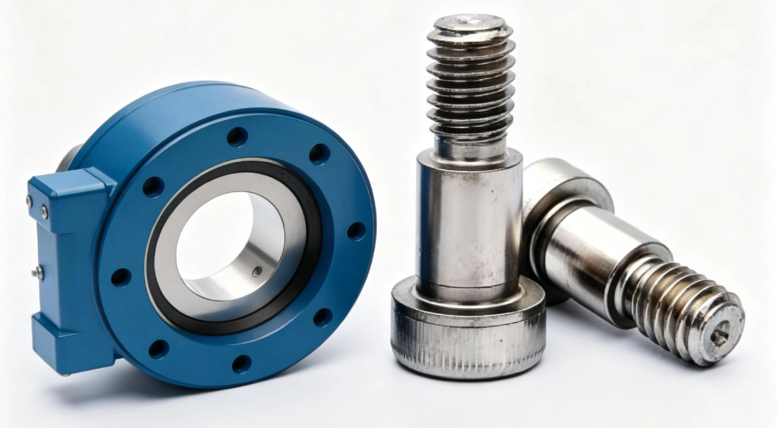
Corrective work should match the evidence. A drive replacement may be justified when internal damage is confirmed, but replacement is not the default answer for every increase in rotational movement. The table below connects likely findings with suitable next actions and limits.
| Supported finding | Appropriate action | How to verify the result | Limit of the action |
|---|---|---|---|
| Loose mounting hardware or damaged mounting contact | Repair the mounting interface using the machine manufacturer’s procedure | Repeat the same reversal test and inspect for renewed movement at the housing-to-frame interface | Does not correct internal gear or bearing damage |
| Flexible frame or load path | Review structural stiffness, load placement, and operating duty with the equipment designer | Compare movement near the drive and at the outer load point under equivalent conditions | Does not prove the drive is fault-free; internal checks may still be needed |
| Input coupling or adapter movement | Repair or replace the affected input-side connection | Observe the input train during controlled reversal after repair | Does not resolve output bearing play or worn gear teeth |
| Localized gear-mesh variation or internal bearing movement | Request technical evaluation before adjustment, rebuild, or replacement | Use inspection findings, position-dependent observations, and application records for comparison | Field adjustment may be unsuitable without product-specific instructions |
| Internal damage confirmed by inspection | Plan repair or replacement using the application load and environment data | Establish a new baseline after installation and document it for future inspections | Replacement alone will not prevent recurrence if mounting or structural causes remain |
When a new or replacement unit is needed, specify the actual duty rather than only the outside dimensions. Load direction, overturning moment, rotation speed, environment, required positioning behavior, mounting arrangement, and drive direction all affect the selection of a Slew Drive.
Luoyang Slewring Bearing Co., Ltd. offers standard products from one set and customized products from five sets. Material selection can include ductile cast iron, alloy steel, stainless steel, or forged alloy steel according to load, speed, and environmental conditions. Protection options are available up to IP66 and anti-corrosion performance up to C4H for suitable industrial environments.
Use Maintenance Records to Prevent a Repeat Fault
The most useful prevention method is trend tracking. Record the same movement check at a repeatable machine position and load condition, rather than relying on memory or an operator’s general impression. A stable reading can remain acceptable, while a changing reading needs investigation.
- Record date, equipment identification, operating hours if available, load condition, and rotational position.
- Describe the symptom in plain terms, such as “housing shifts on reversal” or “free movement occurs only near one position.”
- Photograph witness marks, mounting surfaces, and visible wear before cleaning or repair.
- Retain lubrication records and note any changes in grease type, service interval, contamination, or water exposure.
- Record repair actions separately from confirmed findings. “Bolts retightened” is an action, not proof of root cause.
- Establish a new baseline after confirmed repair or replacement, then compare future inspections to that baseline.
Quality checks during production also matter when reviewing a suspected internal issue. Our ISO 9001:2015-certified facility uses CNC machining centers and CMM three-coordinate inspection. According to our documented quality process, every slewing bearing passes CMM inspection and dynamic load testing before delivery; more detail is available through our Slew Drive Quality Control process.
Application evidence should stay specific. For example, a South Korean port equipment manufacturer placed a repeat order for 20 WEA9-62-25HR single worm slew drives used in port crane systems, with stated tracking precision of no more than 0.15 degrees, IP65 sealing, and self-locking behavior. That case supports the importance of matching drive design to port crane duty, but it does not mean every crane symptom is caused by the drive itself.
Know When to Stop Field Troubleshooting and Escalate
Stop field troubleshooting when movement is worsening quickly, tooth damage is visible, the drive binds or produces grinding noise, mounting surfaces are cracked, fasteners cannot be secured to the required machine procedure, or the source of movement cannot be separated safely. Continued operation under those conditions can turn a repairable condition into a larger equipment problem.
Escalation is also appropriate when internal adjustment is being considered but no product-specific adjustment instruction is available. Preload and gear contact settings affect heat, wear, and rotation resistance. An adjustment made without a verified cause can reduce clearance while creating a new failure mode.
Send the following information for technical review: equipment type, drive model if known, photos of the installation, video of controlled reversal, mounting condition, load position, operating environment, lubrication history, symptom location, and whether the motion changes around the rotation. Luoyang Slewring Bearing Co., Ltd. provides a 2-year extended quality warranty and free replacement for confirmed manufacturing defects, subject to fault confirmation.
Increasing slew drive backlash should be treated as a diagnostic signal, not a single confirmed failure. Check the mounting interface first, locate the movement path, compare several rotational positions, separate gear behavior from bearing movement, and account for structural deflection before selecting the repair method.
Request Your Custom Slew Drive or Bearing Spec
Tell us your load, speed, and environment — receive a tailored 100–5000 mm slewing drive or slewing bearing proposal with 3D drawings within 24 hours.
 WhatsApp

 +8613903880726