



What is slew drive backlash? It is the small amount of free rotational movement that occurs before torque transfers fully through the meshing worm and gear teeth. Some clearance is designed into a drive. The real engineering question is whether the observed movement is stable and acceptable, or whether it points to wear, lost preload, damaged teeth, or movement elsewhere in the machine.
For OEM engineers and reliability teams, this distinction matters because a free-play symptom does not automatically mean the drive has failed. A worm gear unit can show measurable motion and still perform as intended under its specified load and duty cycle. However, increasing motion, poor repeatability, impact noise, or load-sensitive behavior requires a structured inspection before the equipment returns to service.
This article addresses slew drive backlash after a field symptom has been found. It is an evergreen engineering assessment, not a market trend report. The observations apply to worm-driven slewing systems used in equipment such as solar trackers, cranes, turntables, forestry attachments, and heavy machinery, where both drive clearance and mounting stiffness affect positioning behavior.

Start by separating designed clearance from changing free play
Conclusion: Stable, repeatable movement that does not worsen with operating load may be designed gear clearance. The reason is simple: worm gears need operating clearance for lubrication, thermal effects, and tooth engagement. This assessment fits a drive that has shown similar motion since commissioning and still repeats its position reliably. It does not apply when the amount of movement has increased over time or is accompanied by noise, heat, vibration, or unstable positioning.
A worm drive transfers torque through contact between the worm thread and gear teeth. The contact condition is influenced by manufacturing geometry, assembly setting, lubrication, load direction, housing stiffness, and the position of the gear mesh. A small reversal movement can therefore be present even in a properly assembled unit.
Do not judge the drive by hand movement alone. A long boom, panel frame, platform, or attachment can amplify small rotational clearance into a visible movement at the outer edge. The useful measurement is angular or linear movement at a defined point, taken with the same load direction and test method each time.
For example, a solar tracker may appear to move noticeably when the tube is pushed by hand. That observation may come from drive clearance, structural deflection, loose fasteners, bearing clearance, or all four together. The decision should be based on repeatable measured motion at the drive and at the structure, not on a visual impression from the end of a long torque tube.
Luoyang Slewring Bearing Co., Ltd. supplies Slew Drive products for applications where the drive, mounting interface, and load path must be evaluated as one system. Material selection can include ductile cast iron, alloy steel, stainless steel, or forged alloy steel according to load, speed, and environmental conditions. The drive housing is only one part of the positioning system.
Comparison of clearance, preload loss, tooth damage, and non-gear movement
Conclusion: Use a symptom-and-test sequence before labeling the condition as gear wear. The same visible free play can have different causes, and replacing a drive will not correct a loose mounting plate or a worn slewing bearing. This table fits first-level troubleshooting after a free-play report. It does not replace a manufacturer review when internal damage, safety risk, or load-holding concerns are present.
| Possible condition | Typical motion pattern | Load sensitivity | Noise and repeatability | Useful inspection test | Buyer implication |
|---|---|---|---|---|---|
| Designed gear clearance | Small reversal movement in both directions before torque transfers | Usually remains similar under a consistent test load | Quiet operation; return position remains repeatable | Measure reversal movement at the same point, with the same load direction and machine position | Record the baseline and continue monitoring if performance remains acceptable |
| Preload loss or changed mesh setting | Free movement may feel larger than the established baseline | May become more evident during direction reversal or changing torque | Possible reduction in positioning repeatability; noise may or may not occur | Inspect adjustment features only according to the supplied drive instructions; compare with earlier records | Review adjustment feasibility with the supplier before changing any setting |
| Tooth damage or gear wear | Movement, roughness, or resistance may vary through rotation | Often changes at certain positions or under higher torque | Clicking, knocking, rough rotation, or inconsistent return position may occur | Rotate slowly through the working range, inspect lubricant condition, and check for localized rough spots | Stop treating the issue as normal clearance; arrange technical evaluation and consider replacement planning |
| Non-gear rotational play | Movement may appear at the output but originates at bolts, bearing, structure, shaft coupling, or frame | Often changes when the external load direction changes | May produce a metallic shift or visible movement at interfaces | Mark and observe mounting joints, fasteners, bearing interfaces, and structural members while reversing torque | Correct the actual moving interface before changing the drive |
The table shows why direction reversal alone is not enough evidence. A drive with designed clearance can move at reversal and still be suitable for service. By contrast, movement that changes by gear position is a stronger warning because a uniform assembly clearance normally should not create a single rough or loose location in the usable rotation range.
Observed condition versus interpretation: repeated movement at one location is an observation. Localized tooth wear, contamination, or damage are possible interpretations. Inspection of lubricant, tooth contact condition, torque history, and the mounting system is needed before selecting one explanation.
For high-load equipment, the source of apparent play may also be the bearing rather than the worm mesh. A separate Slewing Bearing inspection is appropriate when the platform can rock under moment load, even if the drive’s worm shaft does not show abnormal reversal movement.
Request Your Custom Slew Drive or Bearing Spec
Tell us your load, speed, and environment — receive a tailored 100–5000 mm slewing drive or slewing bearing proposal with 3D drawings within 24 hours.
Use a controlled inspection procedure before adjustment or replacement
Conclusion: Repeatable measurements taken under controlled conditions are more useful than a single free-play check. The reason is that load direction, machine position, structural deflection, and test-point distance can change the result. This procedure fits maintenance teams evaluating an installed unit. It does not apply as a substitute for lockout procedures, lifting plans, or the machine manufacturer’s safety instructions.
- Make the equipment safe. Isolate power, prevent unintended rotation, and remove or control external loads according to the machine safety procedure. A suspended load, wind-loaded panel array, or elevated platform can make a backlash test unsafe.
- Define the symptom. Record whether the concern is poor tracking, impact noise, visible rocking, missed position, delayed reversal response, or a combination. The symptom guides the test and prevents a general “loose drive” report from becoming the final diagnosis.
- Select fixed measurement points. Place a dial indicator or other suitable measuring device at a rigid, repeatable point. Mark the drive housing, mounting face, output interface, and nearby structure so movement at each joint can be observed.
- Apply reversal torque gently in both directions. Use a controlled method that does not overload the equipment. Record movement before output torque transfers in each direction. Do not compare results taken at different radii without converting or clearly labeling the measurement location.
- Repeat at several positions. Test within the actual working range, especially where the symptom occurs. A result that remains consistent supports a clearance or system-level assessment; a result that changes by position needs closer gear and bearing review.
- Inspect the mounting system. Look for movement between housing and frame, output flange and turntable, fastener joints, couplings, and structural members. Verify fastener condition against the machine builder’s specified torque and inspection method.
- Check operating evidence. Review lubricant condition, leakage, contamination, abnormal sound, temperature history if available, and past maintenance records. These facts can change a preliminary “normal clearance” decision into a damage investigation.
- Compare against an agreed baseline. The best baseline is a commissioning measurement from the same machine and test method. If no baseline exists, establish one after inspection and track it at defined service intervals.
A common mistake is measuring at the outer edge of a large structure and assigning all movement to the drive. Another is adjusting a worm mesh before checking the bolts and support frame. A third is treating any clearance as a defect, then creating excessive contact load through an unapproved adjustment.
- Do not tighten an adjustment feature by guesswork. A tighter mesh may reduce reversal movement but can increase friction, heat, and tooth contact stress. Adjustment is suitable only when the drive design provides for it and the manufacturer gives the applicable method.
- Do not ignore load direction. A platform can settle differently under clockwise and counterclockwise torque. Test both directions, because one-way results can hide structural movement.
- Do not inspect only one rotation point. Localized damage can be missed if the test is limited to the parked position.
- Do not replace a drive without inspecting the bearing and frame. This approach fits systems where multiple interfaces can create the same symptom. It does not apply when internal drive damage has already been confirmed by inspection.
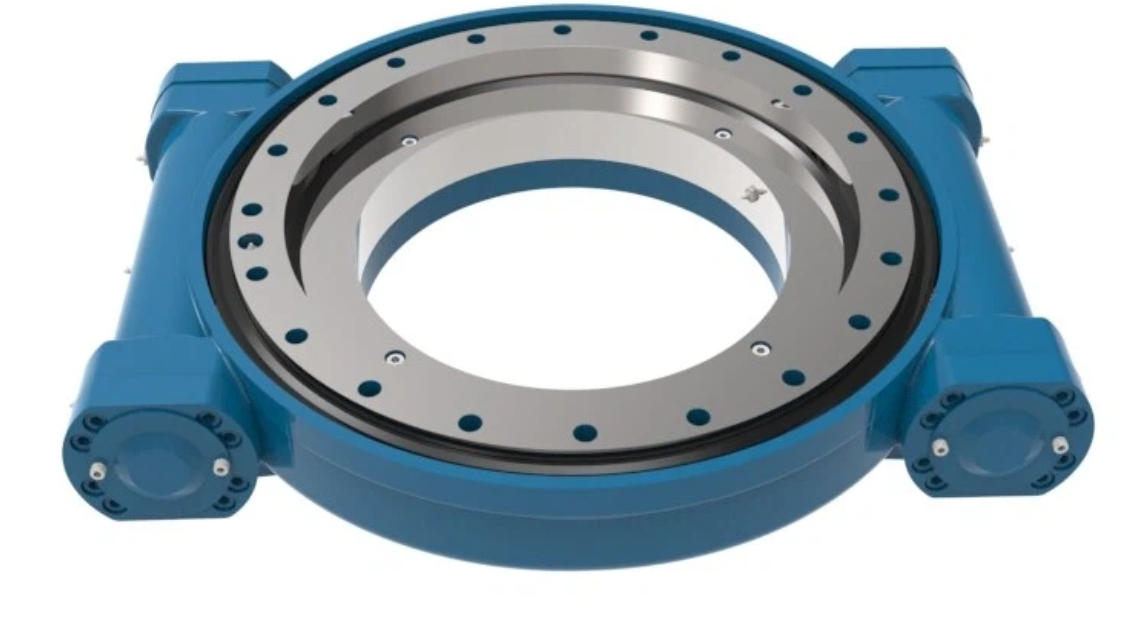
Decide whether monitoring, adjustment, repair review, or replacement fits the evidence
Conclusion: The decision should follow the evidence pattern, not the size of one unreferenced measurement. Stable clearance with reliable positioning supports monitoring. Changing movement, inconsistent rotation, tooth-related noise, or safety-related holding concerns supports prompt technical review. This approach fits OEM service decisions and reliability planning; it does not override equipment-specific limits set by the machine manufacturer.
| Evidence found | Recommended response | Why this response fits | When the response is not enough |
|---|---|---|---|
| Stable movement, quiet operation, repeatable position, no interface movement | Document and monitor | The condition may be intended operating clearance rather than deterioration | Change the plan if the baseline rises, positioning degrades, or operating conditions change |
| Loose bolts, shifting flange, frame deflection, or coupling movement | Correct the moving interface and retest | The observed play is not proven to originate in the gear mesh | Inspect the drive further if movement remains after the interface correction |
| Clearance increase with no rough spots, and adjustment is documented for that model | Request a technical adjustment review | A verified adjustment process may restore the specified contact condition | Do not adjust if tooth damage, abnormal noise, or uncertain drive design is present |
| Rough rotation, localized movement, debris, impact noise, or poor repeatability | Plan technical inspection and replacement assessment | These signs are more consistent with internal damage or wear than stable design clearance | Do not continue operation where safety, load holding, or machine control is affected |
Replacement planning should also consider application duty. A low-speed manual positioning fixture and a crane or tracked solar system do not carry the same consequence of lost repeatability. For tracked systems, the question is whether the position error affects output or process accuracy. For lifting and personnel-adjacent equipment, the question also includes safe holding, machine control, and the equipment builder’s inspection rules.
Where torque reversal accuracy is a leading requirement, drive configuration deserves review. A Double Worm Slew Drive can be considered for applications needing torque shared through two worm arrangements, but it is not an automatic cure for structural looseness or bearing clearance. The suitable configuration depends on actual loads, duty cycle, mounting stiffness, environment, and required positioning behavior.
Luoyang Slewring Bearing Co., Ltd. has supplied double worm drives for demanding applications, including WED14-86-25BHR.5 units for forestry grapple machines in British Columbia, Canada, where the stated precision requirement was no more than 0.13°. That project is a specific application example, not a blanket performance statement for every drive or machine installation.
Specify inspection evidence and supplier support before the next purchase
Conclusion: A purchase specification should require a clear acceptance method for free play, mounting condition, and operating performance. The reason is that “low backlash” by itself is not a complete requirement. This is especially useful for OEMs developing a new machine or replacing an existing drive across several units. It does not remove the need for the system designer to define loads, structure, safety functions, and position requirements.
Use the following buyer checklist when requesting a replacement drive, evaluating a sample, or developing a customized unit:
- Define the application: solar tracker, crane, turntable, forestry attachment, marine equipment, or another mechanism.
- State the actual load directions, external moment loads, operating speed, duty cycle, and environmental exposure.
- Describe whether reverse-direction positioning, self-locking behavior, or continuous rotational accuracy is the primary concern.
- Provide the mounting drawing and identify the stiffness of the support structure and output connection.
- Ask how clearance is checked during assembly and what inspection record is available for the supplied unit.
- Confirm whether the proposed model has an approved adjustment method and who is authorized to perform it.
- Set a field acceptance test with a defined measurement point, torque direction, machine position, and load condition.
- Request a technical proposal when the existing symptom may result from combined drive, bearing, and structure movement.
Our ISO 9001:2015 certified facility can provide technical proposals within 24 hours, while standard production is stated at 9 days and rapid prototyping at 3 days for suitable projects. Standard product MOQ is 1 set, and customized product MOQ is 5 sets. These options help an OEM test a replacement or a revised design before committing to a larger production release.
Inspection evidence also matters after sourcing. Luoyang Slewring Bearing Co., Ltd. states that every slewing bearing passes CMM three-coordinate inspection and dynamic load testing, with a 2-year extended quality warranty and a 48-hour technical response. Review the available Slew Drive Quality Control information alongside the machine-level acceptance plan, because component inspection cannot verify a weak machine frame or an incorrect installation.
For a case-specific reference, a South Korean port equipment manufacturer placed a repeat order for 20 WEA9-62-25HR single worm drives for port crane systems. The stated requirements included tracking precision of no more than 0.15°, IP65 sealing, and self-locking. That example shows why backlash evaluation must be tied to a stated machine requirement rather than judged as an isolated visual symptom.
The practical rule is direct: measure the movement, locate the moving interface, repeat the test across the operating range, and compare the result with the machine’s functional requirement. Normal clearance is stable and understood. Wear is usually changing, position-dependent, noisy, rough, or linked to declining repeatability. When the evidence is uncertain, preserve the records and request a technical review before adjustment or replacement.
Request Your Custom Slew Drive or Bearing Spec
Tell us your load, speed, and environment — receive a tailored 100–5000 mm slewing drive or slewing bearing proposal with 3D drawings within 24 hours.
 WhatsApp

 +8613903880726