



What is a slew drive? A slew drive is a compact rotary transmission unit that combines a slewing bearing, gear system, housing, and mounting interface to rotate a load while carrying radial, axial, and overturning forces.
The safe amount of slew drive clearance is not one universal number. It depends on where the clearance is measured, whether the drive is unloaded or loaded, the direction of the applied force, and the equipment’s required positioning accuracy.
A clearance value that appears acceptable on a bench can become unsafe after a boom, panel frame, platform, or offset load creates an overturning moment. Design engineers should therefore evaluate radial movement, axial movement, and gear backlash as a connected system rather than treating any one measurement as the full condition of the drive.
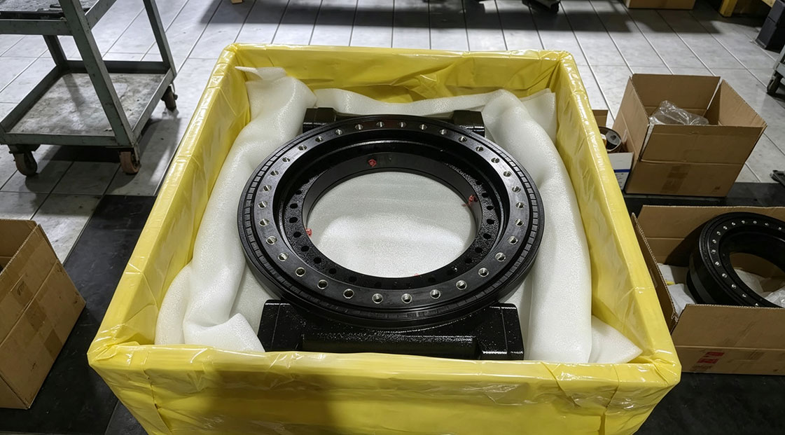
Start With the Load Case Instead of a Single Clearance Number
The first question is not “What clearance is normal?” It is “What motion can the machine safely tolerate at its maximum working load, maximum reach, and required positioning accuracy?” This distinction matters because the same small movement at the drive may become much larger at the tip of a long boom or solar tracker structure.
For example, a crane platform can tolerate a different motion pattern than a solar tracking array. A crane must maintain stable load handling and controlled rotation, while a tracker may need repeatable angular positioning to maintain energy capture. The correct acceptance limit must match the application, not a generic factory measurement.
| Clearance Type | What It Describes | What the Operator May Notice | Why It Must Be Checked Under Load |
|---|---|---|---|
| Radial clearance | Side-to-side movement between rotating and fixed parts | Wobble, changing gear contact, uneven motion | Offset loads can shift the rolling elements toward one side of the bearing raceway |
| Axial clearance | Movement parallel to the rotation axis | Lift, drop, rocking, or mounting face separation | Overturning load can increase movement on the unloaded side of the bearing |
| Gear backlash | Lost motion between mating gear teeth | Delay when reversing direction, position error, impact during starts and stops | Bearing deflection can alter gear mesh and change backlash during rotation |
| Elastic deflection | Temporary movement of the housing, mounting structure, and gear system | Different readings at different load levels | It can be mistaken for permanent bearing wear if the test method is poorly controlled |
The practical conclusion is simple: unloaded clearance is only a reference measurement. It fits incoming inspection, storage checks, and baseline maintenance records, but it does not by itself confirm loaded suitability for a crane, excavator, steering platform, or long-span tracker.
When evaluating a Slew Drive, ask the supplier to review the full duty cycle. Include the maximum vertical load, side load, offset distance from the rotation center, rotational speed, reversing frequency, mounting arrangement, and required angular accuracy.
Why overturning moment changes the answer
An overturning moment occurs when the load acts at a distance from the rotation center. A cantilevered boom, crane jib, tilted solar array, or off-center work platform creates this condition. The greater the offset distance or applied load, the more the bearing and housing are asked to resist a tipping action.
Under this force, rolling elements on one side of the bearing carry more load while the opposite side may unload. Radial and axial movement can then appear together, even when the system had only one obvious direction of movement during an unloaded hand check.
Do not assume that a larger internal clearance solves this problem. Extra clearance may prevent preload-related friction in some designs, but it can also increase rocking and gear position variation. The best arrangement is the one designed for the actual load spectrum and mounting stiffness.
Boundary Conditions for Radial, Axial, and Backlash Clearance Under Overturning Load
The boundary between acceptable movement and unsafe movement is reached when clearance no longer supports the machine’s functional requirements or begins to change load sharing in an uncontrolled way. This boundary is application-specific, which is why a supplier should not issue a safe loaded limit without the load case and mounting details.
The table below shows how each type of movement changes as overturning load rises. It also explains when a maintenance team should stop treating the reading as a normal adjustment issue and start investigating design load, bearing condition, fasteners, gear mesh, or mounting distortion.
| Parameter | Behavior as Overturning Load Increases | Boundary That Requires Engineering Review | What Can Be Unsafe |
|---|---|---|---|
| Radial clearance | May become directional as the load pushes the rotating ring sideways | Movement differs sharply by measurement position, increases under the same test load, or causes unstable gear engagement | Side movement that changes tooth contact, causes rubbing, or produces visible rotation-center shift |
| Axial clearance | One side can compress while the opposite side lifts or unloads | Measured lift or drop prevents stable support, changes mounting face contact, or creates repeatable rocking | Loss of stable contact that transfers force into bolts, housing edges, or gear components |
| Gear backlash | Can increase or decrease as the bearing tilts and gear center distance changes | Backlash varies around the rotation, reversals produce impact, or tooth contact shifts toward an edge | Excess lost motion for positioning or tight mesh that creates binding under load |
| Combined movement | Radial and axial motion can combine into angular tilt | The output flange rocks while rotating, even when individual measurements seem modest | Misalignment that overloads rolling elements and causes irregular gear contact |
Radial clearance becomes a greater concern when the application has a high side load or a long lever arm. A truck-mounted crane, forestry grapple, and excavator attachment can all impose changing side force as the working position changes. A measurement taken only at the neutral position may miss the worst condition.
Axial clearance becomes more important when vertical support and tilt stability are the main requirements. This includes turntables, aerial work platforms, and suspended loads. If the drive can rock between loaded and unloaded states, the machine may show position drift even if the gear reducer itself is operating normally.
Backlash should never be assessed as a fixed value detached from bearing behavior. In a worm-driven unit, worm-to-gear contact depends on the relative position of the components. If the bearing tilts under load, a backlash reading at one rotational position may not represent the tightest or loosest mesh elsewhere in the rotation.
The unsafe condition is not simply “high clearance.” Negative operating clearance can also be unsafe when deflection or thermal effects make the bearing or gear mesh too tight. Binding, high turning resistance, abnormal heat, or a tight point during rotation require investigation rather than automatic adjustment.
For applications with repeated reversing load, use a test that captures both directions. A single-direction rotation test can hide backlash and impact problems that become visible only when the motor changes direction.
Measure Loaded Movement With a Repeatable Procedure
A useful inspection method separates bearing movement, gear lost motion, and mounting movement. If these are mixed together, the maintenance team may replace a good drive when the real issue is a distorted base plate, loose fasteners, or flexible equipment structure.
- Define the test condition. Record the load, load position, rotational position, drive orientation, and whether the machine is supported, suspended, or hydraulically held. Repeatability starts with a documented setup.
- Inspect the mounting interface first. Check for loose bolts, damaged threads, uneven contact surfaces, cracked welds, plate distortion, and debris between mounting faces. Do not interpret clearance data before this step.
- Set a stable reference point. Place a dial indicator or suitable measuring device between a fixed structure and the rotating output flange. The reference must not move with the part being measured.
- Measure radial movement. Apply controlled side force in opposite directions where the equipment allows it. Record movement at several rotational positions because localized wear or load-zone changes can produce different results.
- Measure axial movement. Apply the specified lifting and lowering force safely, then record vertical movement. Test under representative load direction, not only with the assembly unloaded.
- Measure reversal lost motion. Mark the output position, reverse the input direction under controlled conditions, and observe the delay before output movement. Compare readings around the full rotation.
- Compare loaded and unloaded results. A meaningful increase under the same controlled load indicates that bearing support, mounting stiffness, or gear engagement requires further review.
- Review the trend, not one reading. Compare the result with the commissioning baseline and prior inspection records. A changing pattern is often more useful than an isolated measurement.
This procedure fits commissioning and planned maintenance. It does not replace the supplier’s load rating review or a machine-level safety assessment, especially where personnel lifting, suspended loads, or high-consequence positioning are involved.
Luoyang Slewring Bearing Co., Ltd. can support the review with a technical proposal within 24 hours when the duty details are available. Our engineering team works with load, speed, environment, and required motion conditions to select materials and drive configurations rather than treating clearance as an isolated catalog item.
For bearing-centered inspection work, the Slewing Bearing configuration also matters. Single-row, double-row, crossed-roller, and three-row roller arrangements distribute radial, axial, and overturning forces differently, so the inspection method should match the bearing structure.
Request Your Custom Slew Drive or Bearing Spec
Tell us your load, speed, and environment — receive a tailored 100–5000 mm slewing drive or slewing bearing proposal with 3D drawings within 24 hours.
Separate Bearing Clearance From Gear Backlash Before Adjusting Anything
A frequent mistake is to call every reversal movement “backlash.” The observed movement may come from bearing clearance, mounting plate flex, bolt joint movement, worm gear contact, couplings, motor gearboxes, or a combination of these sources.
Adjusting a worm mesh to remove apparent lost motion can make the actual problem worse. If the movement came from bearing tilt or a flexible structure, reducing gear backlash may create a tight mesh at another rotational position or under a different load direction.
- Mistake: checking only with no working load. This can be acceptable for a receiving inspection baseline, but it does not confirm behavior under an offset or overturning load.
- Mistake: measuring at one clock position. It does not apply when the drive experiences uneven loading, localized wear, or changing gear mesh around the rotation.
- Mistake: treating all backlash as bearing wear. Check couplings, motor reducers, mounting joints, and gear engagement before assigning the cause to the slewing bearing.
- Mistake: tightening the worm adjustment without a full rotation test. This does not apply to a system with variable gear mesh. Test the complete operating rotation for tight spots and turning resistance.
- Mistake: ignoring bolt preload and mounting flatness. A drive cannot show stable loaded behavior if the mounting surfaces move or the fasteners do not maintain joint integrity.
- Mistake: selecting by static load alone. This does not apply to equipment with frequent starts, stops, reversals, shock loading, or long lever arms. The duty cycle must be included.
Use separate acceptance records for bearing movement and gear reversal motion. That creates a clearer service history and helps identify whether the condition is progressing in the bearing system, the gear train, or the equipment structure.
Our Slew Drive Quality Control process includes CMM three-coordinate inspection and dynamic load testing for every slewing bearing. Luoyang Slewring Bearing Co., Ltd. also provides a 2-year extended quality warranty and technical response within 48 hours for confirmed product support needs.
Select the Drive Configuration Around Accuracy, Load Direction, and Duty Cycle
The right drive is not always the smallest unit that carries the stated load. A compact unit may fit a light, steady application, while a machine with high overturning force or frequent direction changes may need a different bearing arrangement, larger mounting interface, or dual-worm design.
| Application Condition | Selection Direction | Reason | Limit of This Recommendation |
|---|---|---|---|
| Single-axis solar tracker with controlled, low-speed rotation | Evaluate a spur gear slew drive where the structural load case fits | Positioning needs and environmental protection must be reviewed with the tracker structure | Do not use the application label alone; panel size, wind load, and support spacing still control the selection |
| Crane or offset platform with reversal movement | Review worm-driven options and loaded backlash behavior | Reversal motion and overturning force can affect gear contact and output stability | Self-locking behavior and final safety design must be reviewed for the complete machine |
| Heavy-duty steering or mining equipment | Consider a double-worm configuration when the load case requires greater support and control | Two worm engagement points can suit demanding cyclic load conditions | It is not automatically required for every high-load machine; the bearing, mounting, and duty cycle still decide |
| Custom equipment with unusual flange, environment, or motion requirements | Use a customized design review | Standard interfaces may not control deflection, sealing, corrosion exposure, or installation constraints | Customization requires complete load and interface data before a design can be confirmed |
For high-cycle equipment, a Double Worm Slew Drive may be considered when the application needs support for demanding cyclic loading and controlled rotation. It should not be selected merely to compensate for a flexible or poorly prepared mounting structure.
Real application context matters. An Australian heavy equipment manufacturer selected HWE21-94-25HR.1 double worm slew drives for mining excavators, while a Houston engineering machinery manufacturer used 150 units of WED17-104-25HR double worm drives for heavy-duty wheel steering systems. These cases show where double-worm drive arrangements can fit, but they do not create a universal sizing rule.
For precision-sensitive work, verify the needed tracking or positioning result at the machine output, not only at the drive input. Luoyang Slewring Bearing Co., Ltd. supplied 20 WEA9-62-25HR single worm drives for South Korean port crane systems with stated tracking precision of no more than 0.15 degrees, IP65 sealing, and self-locking. That result applies to the stated customer configuration and should not be transferred unchanged to another crane design.
Use This Review Checklist Before Commissioning or Replacing a Drive
A safe decision requires more than a clearance reading. The checklist below gives purchasing teams, engineers, and maintenance personnel the information needed to request a useful technical review.
- Maximum radial load, axial load, and overturning load, including the load direction.
- Distance from the load center to the rotation center.
- Static, operating, shock, and reversing load conditions.
- Required output positioning accuracy and allowable reversal movement at the machine level.
- Rotational speed, duty cycle, starts, stops, and direction changes.
- Operating environment, including contamination, moisture, corrosion exposure, and temperature conditions.
- Mounting flange dimensions, bolt pattern, surface flatness condition, and structure stiffness.
- Loaded and unloaded movement readings, measured at several rotational positions.
- Evidence of gear tooth contact changes, tight spots, abnormal sound, or uneven resistance.
- Commissioning baseline records for future maintenance comparison.
Luoyang Slewring Bearing Co., Ltd. has focused on slew bearing and slew drive research and development for more than 15 years and has supported more than 2,000 heavy-equipment projects. The company operates six production lines in an 8,000 square meter manufacturing facility, with standard production cycles of 9 days and sample orders available for testing and evaluation.
When the application requires a nonstandard mounting layout, special environment protection, or a load condition that changes substantially through rotation, consider a Customized Slew Drive. Provide the complete working condition rather than asking for a clearance value alone; that is the practical way to determine whether loaded movement remains within the machine’s safe operating boundary.
Request Your Custom Slew Drive or Bearing Spec
Tell us your load, speed, and environment — receive a tailored 100–5000 mm slewing drive or slewing bearing proposal with 3D drawings within 24 hours.
 WhatsApp

 +8613903880726