



What is slew drive backlash? It is the free rotational movement seen when the input direction reverses before the output ring begins to move under load. For field technicians and machine builders, the real question is not whether some free movement exists, but whether that movement has grown enough to create unacceptable positioning drift at the machine’s working point.
This guide shows how to measure slew drive backlash on the machine using a dial indicator, a controlled reversal method, and a simple drift calculation. The outcome is test evidence that can support a preload review, an internal inspection request, or a service escalation instead of relying on operator feel alone.
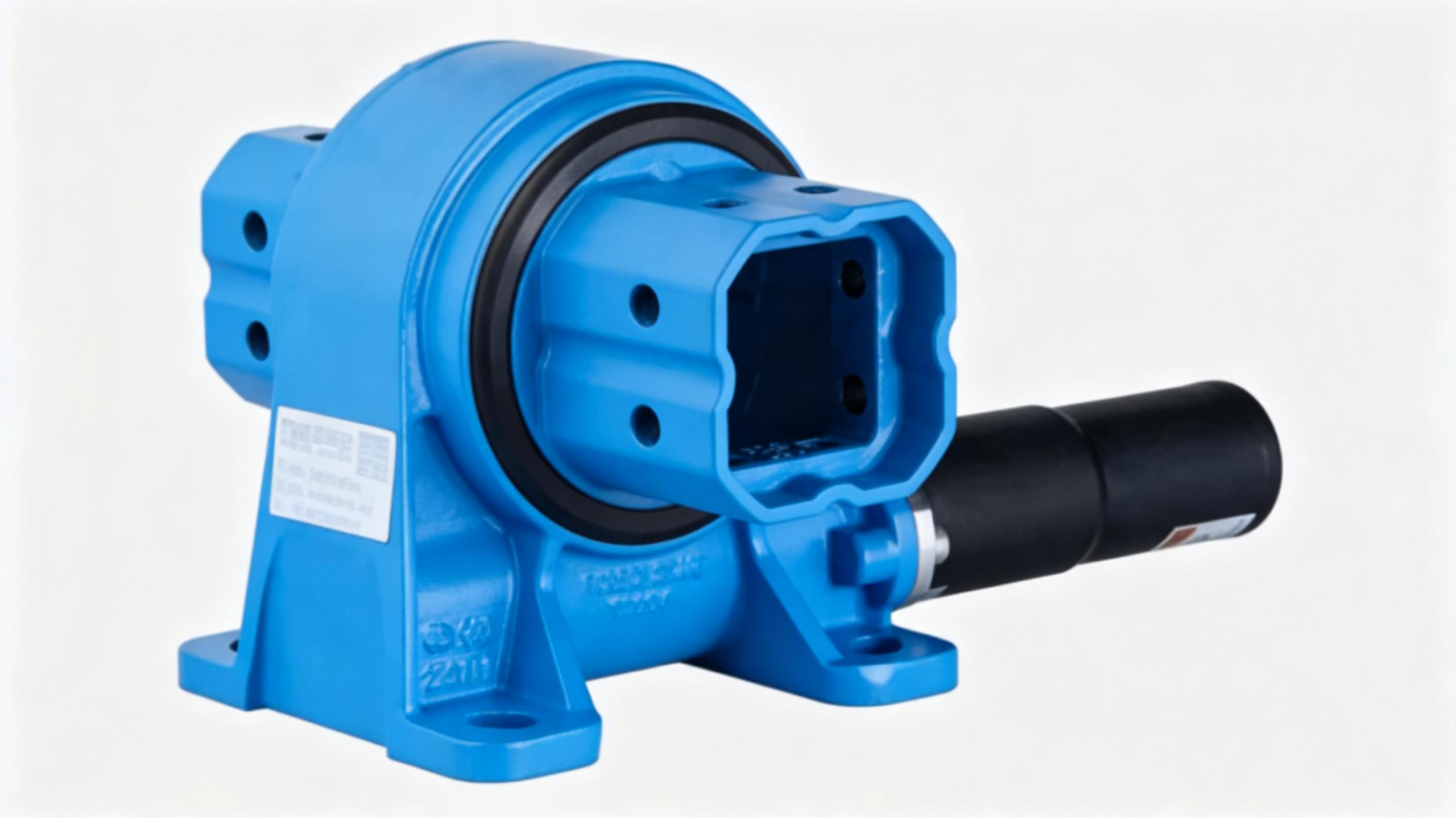
Define the test result before mounting the indicator
Start by defining the positioning function that matters. A solar tracker may need repeatable panel alignment, while a crane platform may need controlled stopping during directional reversal. The same measured movement can be acceptable in one machine and unacceptable in another because the working radius, payload behavior, and allowable angular error are different.
Do not use the test to declare that a drive is good or bad without a comparison reference. Compare the result with the machine builder’s allowable positioning error, the original inspection record, the drive supplier’s service criteria, or a known-good unit tested with the same method.
| Test question | What to record | Why it affects the decision | Limit of the result |
|---|---|---|---|
| How much free output movement occurs? | Dial indicator travel during direction reversal | Shows total lost motion at the chosen test radius | Does not isolate worm, bearing, mount, and structure effects |
| How much angular drift can it create? | Measured travel and test radius | Relates movement to the machine’s positioning task | Small-angle conversion is an approximation |
| Is the condition stable? | Repeated readings in both directions | Separates repeatable clearance from erratic movement | Cannot replace an internal damage inspection |
| Is service action justified? | Test record, load condition, and reference limit | Creates evidence for engineering review | Final acceptance belongs to the machine requirement |
The reading is normally a system measurement. It can include clearance in the worm mesh, slewing bearing internal movement, loose mounting bolts, flexible brackets, pinion couplings, and deflection in the test arm. That is still useful because the machine experiences the combined movement, but it means that changing worm preload before checking the mounting system can solve the wrong problem.
For an enclosed Worm Gear Slew Drive, direction reversal is especially useful because the test follows the normal force path through the worm and output ring. The method fits field checks, incoming inspection, and troubleshooting after operators report overshoot, inconsistent stops, or drift after reversal.
Prepare the machine so the reading is repeatable
Park the machine on stable ground and place the rotating structure in a safe, accessible position. Isolate power according to the machine’s lockout procedure so the drive cannot start while hands, fixtures, or instruments are near the rotating assembly. If hydraulic or electrical braking can hold the structure, release or account for it only when the approved service procedure allows.
Use a dial indicator with enough travel to capture the expected movement without reaching its end of stroke. You also need a rigid magnetic base or clamped fixture, a clean contact point on the rotating member, a measuring tape or steel rule, and a log sheet. A marker for identifying the test point is helpful when readings must be repeated after maintenance.
- Choose a tangential test point: Select a point on the rotating output structure where the indicator tip can move in the direction of rotation. A tangential setup measures arc movement directly and makes drift conversion straightforward.
- Measure the radius: Record the distance from the center of rotation to the indicator contact point. Use the same radius in every repeat test. A radius error changes the calculated angular result.
- Mount the indicator base on the stationary side: Attach it to the non-rotating frame, not the rotating platform. If both the base and contact point move together, the indicator can hide actual movement.
- Remove loose external items: Secure tools, hoses, cable loops, and movable guards that could push against the rotating structure during reversal.
- Set the operating load condition: Record whether the test is unloaded, under a known fixture load, or carrying normal equipment. Do not compare an unloaded reading directly with a loaded baseline without noting the difference.
Check the fasteners and structure before blaming internal clearance. Look for visible bolt movement, damaged mounting faces, cracked brackets, or a test arm that flexes when force is applied. If the indicator value changes when a mounting bolt or bracket is touched, stop and correct that condition before continuing.
Use the same load direction for every reading. Gravity can preload the system differently at different boom angles, platform positions, or payload states. A crane, excavator attachment, or tracker frame may show a different result after repositioning even when the drive itself has not changed.
Run a repeatable dial-indicator test and convert movement into drift
This procedure converts measured free movement into an application-relevant angular positioning result. It is designed to show what the rotating structure does during a controlled reversal, not to produce a theoretical worm-shaft-only value.
- Place the output at the intended inspection position. Use a position that represents the reported problem, such as the normal stopping angle or the part of travel where drift is observed. Record the machine position because structural loading can change around the rotation path.
- Apply light force in the first rotational direction. Move the output slowly until resistance is felt and hold that direction without bouncing the structure. This seats the drivetrain on one flank of its clearance.
- Zero the dial indicator. Confirm the indicator tip is close to the middle of its travel and square enough to the tangential movement to avoid side loading. Record the radius from the rotation center to the contact point.
- Reverse force gradually. Apply force in the opposite rotational direction only until resistance is felt again. Do not force the assembly past its natural stop or use shock loading, because elastic deflection can inflate the reading.
- Record the total indicator movement. This is the free tangential travel at that radius. Write down the value, test direction, load state, machine position, and whether the motion was smooth or stepped.
- Repeat at least three times. Return to the original direction before each reversal. Similar values support a repeatable result; widely scattered values point to an unstable setup, varying load path, loose attachment, or intermittent internal contact.
- Convert the movement to angular drift. Divide tangential movement by radius using the same unit, then convert radians to degrees. For small movements, angular drift in degrees is approximately: measured movement ÷ test radius × 57.3.
For example, assume the indicator shows 2 mm of free tangential movement at a 1,000 mm test radius. The estimated rotation is 2 ÷ 1,000 × 57.3, or about 0.115 degrees. At a farther working point, that same angular error creates more linear position shift, which is why a long boom, antenna arm, or panel row may reveal drift that seems minor at the drive.
| Observed condition | Likely meaning | Immediate recovery action |
|---|---|---|
| Nearly identical readings in repeated tests | Free movement is repeatable under the selected condition | Compare the converted angle with the machine’s allowed error |
| Reading increases each reversal | Structure may be settling, or a fastener or fixture may be moving | Inspect mounts and indicator base, then restart the test |
| One direction reads much higher | Load direction, gravity, or contact condition is affecting the system | Document both directions and repeat at the same machine position |
| Sudden jump or clicking during reversal | Possible intermittent engagement, external interference, or structural slip | Stop the test and inspect before applying more force |
This method is more useful than stating that a drive “has play.” It gives a traceable movement at a known radius, an estimated angular effect, and a repeatable record that an engineering or service team can review. It does not identify the exact internal clearance by itself, so do not treat the result as permission to reset preload without the supplier’s service instruction.
Request Your Custom Slew Drive or Bearing Spec
Tell us your load, speed, and environment — receive a tailored 100–5000 mm slewing drive or slewing bearing proposal with 3D drawings within 24 hours.
Separate drive clearance from mounting and structural movement
A high reading does not automatically mean the worm mesh is worn. First, repeat the reversal test with the indicator moved to another point on the same rotating member. If the converted angular value is similar at different radii, the movement is more likely rotational; if the values differ sharply, local bracket flex or contact geometry may be influencing the result.
Next, place a second indicator where possible to observe a suspected source. One indicator can remain at the outer tangential test point while another monitors a mounting interface, gearbox bracket, or support frame. Movement at the second indicator during reversal provides evidence that the assembly, rather than only the gear set, is contributing to the drift.
Common measurement mistakes that create misleading readings
- Using a radial indicator direction: A radial tip direction can understate rotational movement. Set the indicator so its plunger follows the tangential path of the test point.
- Changing the test radius: A 2 mm movement has a different angular meaning at 500 mm than at 1,000 mm. Record the radius every time.
- Reversing with a sudden push: A sharp push adds structural flex and can make the result look worse than the actual free movement. Reverse slowly until resistance is felt.
- Testing with an unrecorded payload: Load changes can alter contact forces. Record payload, boom position, and orientation so later readings can be compared.
- Ignoring mounting bolt or frame movement: Internal adjustment cannot correct a loose interface. Inspect and correct external movement first.
- Comparing different machine positions as if they were identical: Gravity and offset load can change the result. Repeat at the same angle before declaring deterioration.
These checks matter when deciding whether to investigate the drive, the supporting Slewing Bearing, or the machine structure. A slewing system is a load path, not a single component. The best service record identifies where the measured movement occurred and what conditions produced it.
Use the evidence to choose the next maintenance action
If the measured movement is repeatable and the converted drift remains within the machine’s stated positioning allowance, document the baseline and continue periodic checks. This approach fits equipment that has no operating symptoms but needs an inspection history. It does not mean the result will remain stable under a different payload or mounting condition.
If the value exceeds the application allowance, or if the reading has increased from a comparable baseline, do not begin with an arbitrary preload adjustment. Confirm mounting torque and support condition using the machine documentation, then provide the test record to the equipment designer or drive supplier. Preload changes can affect friction, heat, wear behavior, and the load capacity available to the mechanism.
For a machine builder, specify the test method in the maintenance manual so field readings can be compared across units. Include the test radius, indicator orientation, machine position, payload condition, reversal force method, and allowable angular drift. A Customized Slew Drive review may be appropriate when the machine needs a different drive arrangement, output interface, environmental protection level, or positioning requirement than a standard design can support.
Luoyang Slewring Bearing Co., Ltd. can support this evidence-based process with a technical proposal within 24 hours and a 48-hour technical response. Our ISO 9001:2015 certified facility uses CMM three-coordinate inspection and dynamic load testing for every slewing bearing, while our standard product MOQ is one set for evaluation work and sample orders are welcome.
For context, repeatable positioning is already a documented requirement in demanding equipment. A British Columbia forestry equipment manufacturer selected WED14-86-25BHR.5 double worm slew drives for grapple machines with stated precision of no more than 0.13 degrees, while a South Korean port equipment manufacturer placed a repeat order for WEA9-62-25HR drives used in port crane systems with stated tracking precision of no more than 0.15 degrees. Those case figures are application-specific, not universal acceptance limits for every machine.

Complete a service-ready inspection record
A completed test should allow another technician to repeat it without guessing. Include the drive model, serial information if available, date, machine position, load condition, test radius, indicator travel, calculated angular drift, and readings from each repetition. Add photos showing indicator orientation and the stationary mounting point.
Use the checklist below before releasing the machine or escalating the result. It turns a field observation into evidence that a design, quality, or service team can evaluate.
- Machine was secured and the rotating assembly could not start unexpectedly.
- Indicator base was fixed to a non-rotating structure.
- Indicator contact direction was tangential to output rotation.
- Test radius was measured and recorded.
- Force was applied slowly in both directions until resistance was felt.
- At least three readings were taken under the same condition.
- Payload, machine angle, and test location were recorded.
- Mounting interfaces were checked for visible movement.
- Measured travel was converted into estimated angular drift.
- The result was compared with a documented machine requirement or baseline.
When the record is complete, the next action becomes clearer: keep monitoring, correct an external mounting issue, request supplier guidance, or plan a component inspection. That is the practical value of measuring slew drive backlash before operators experience repeated drift, missed positions, or unplanned downtime.
Request Your Custom Slew Drive or Bearing Spec
Tell us your load, speed, and environment — receive a tailored 100–5000 mm slewing drive or slewing bearing proposal with 3D drawings within 24 hours.
 WhatsApp

 +8613903880726