



What is a slew bearing replacement procedure? It is the controlled removal, installation, inspection, and acceptance process used to confirm that a replacement bearing is mounted correctly and can rotate safely under its intended load.
For cranes, excavators, rotating platforms, and similar equipment, the main commissioning question is not simply whether the new bearing turns. The real question is whether the mounting structure, bolt preload, bearing position, gear mesh, and rotational behavior work together without creating an early failure risk.
A proper slew bearing replacement procedure separates two types of evidence. Bolt-torque checks confirm mounting integrity, while runout checks confirm rotational alignment and structural condition. Backlash and gear-contact checks then show whether the drive pinion and bearing gear are meshing correctly.
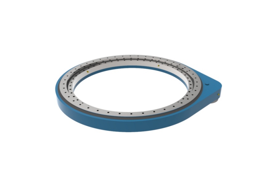
Start by separating mounting integrity from rotational performance
The most common acceptance mistake is treating one good measurement as proof that the entire installation is correct. A correctly torqued bolt does not prove that the bearing is seated flat, and a low runout reading does not prove that all mounting bolts have the required preload.
Mounting integrity is mainly about the connection between the bearing rings and the machine structure. Rotational performance is mainly about how the installed assembly behaves as it turns through a full revolution under controlled conditions.
Use bolt-torque verification to answer whether the fasteners are applying the required clamping force. Use runout measurement to answer whether the bearing, mounting faces, and supporting structure remain acceptably aligned during rotation.
What bolt torque tells the commissioning team
Bolt torque is an indirect method for controlling bolt preload. The preload clamps the slewing bearing ring against the mounting surface and helps prevent relative movement between the ring and the frame.
If torque is too low, the ring can shift under cyclic load. That movement can enlarge bolt holes, damage mounting faces, reduce gear mesh consistency, and eventually cause bolt fatigue.
If torque is too high, the fastener may be overstressed or the threads may be damaged. A high torque value is not automatically better, so the installation team should use the fastener grade, lubrication condition, tightening sequence, and torque value specified by the bearing or equipment manufacturer.
What runout tells the commissioning team
Runout is the change in position measured while the bearing assembly rotates. Depending on the test setup, technicians may measure axial movement, radial movement, or movement at a reference point on the rotating structure.
Excessive runout can point to uneven mounting faces, trapped debris, distorted support structures, incorrect shimming, or a bearing that is not fully seated. It can also be caused by a damaged or worn mating structure that was not corrected before the replacement bearing was installed.
A runout reading must be taken at defined locations and through a full rotation. One reading at one angular position cannot represent the condition of a full slewing ring.
For heavy-duty applications, the replacement unit should match the load path of the original design. A Heavy load slewing bearing may require more attention to mounting stiffness and surface condition than a lightly loaded rotating platform because local structural deflection can affect bearing behavior.
Compare pre-start and post-install inspection measurements before releasing equipment
The same four checks should be used before the machine starts and after installation, but the purpose changes. Pre-start inspection looks for installation errors while the machine is stationary. Post-install inspection looks for changes that appear after controlled rotation, settling, and functional testing.
| Measurement | Pre-start check reveals | Post-install check reveals | What the result affects | When the check alone is not enough |
|---|---|---|---|---|
| Bolt torque | Whether bolts were tightened in the required sequence and to the specified condition before loading. | Whether the bolted joint shows signs of settling, loss of preload, or uneven clamp behavior after initial operation. | Ring retention, load transfer, fatigue resistance, and mounting-face stability. | Torque cannot confirm that the mounting faces are flat or that the bearing rotates without alignment issues. |
| Runout | Whether the installed ring and reference structure show abnormal movement before functional operation. | Whether controlled rotation exposes structural distortion, seating changes, or position-dependent movement. | Rotation quality, gear mesh consistency, load distribution, and component clearance. | Runout does not prove every bolt is properly preloaded or that gear teeth contact correctly. |
| Backlash | Whether the pinion-to-ring gear clearance is present and whether the drive can rotate without tooth binding. | Whether backlash remains consistent after initial movement and whether high or low spots appear around the ring. | Drive smoothness, tooth loading, positioning behavior, and risk of tooth interference. | Backlash cannot show the full contact location across the tooth face. |
| Gear-contact pattern | Whether the pinion is positioned to contact the intended area of the ring gear tooth face. | Whether rotation produces uneven tooth contact, edge loading, or changing contact caused by mounting distortion. | Gear tooth life, noise, heat generation, and drive reliability. | A contact pattern should be interpreted with backlash and runout, not treated as an isolated pass/fail mark. |
The practical difference is simple. Pre-start measurements prevent an obvious assembly error from reaching operation, while post-install measurements verify that the assembly still behaves correctly after movement has loaded the joint and exercised the gear mesh.
Do not compare readings taken under different conditions as though they mean the same thing. A reading taken with the boom lowered, for example, may not be directly comparable with a reading taken under a different machine position or loading condition.
Use a controlled inspection sequence instead of checking measurements in isolation
The most useful acceptance method follows the physical order of the installation. First confirm the support structure, then secure the bearing, then evaluate rotation, and finally set and verify the gear mesh.
- Confirm the replacement bearing identification. Verify the bearing type, mounting-hole pattern, gear position, and interface dimensions against the equipment requirement. Do not assume that a visually similar ring has the same load capacity or gear geometry.
- Inspect the mounting faces before placing the bearing. Remove old sealant, rust, burrs, weld spatter, dirt, and trapped grease. Check for visible dents, corrosion pits, damaged threads, or local deformation that can prevent full contact.
- Support the bearing correctly during lifting. Keep the ring stable and avoid impacts. A slewing bearing is a precision load-carrying component, not a lifting fixture for the machine structure.
- Install bolts using the required tightening pattern. Tighten in a cross-pattern or another approved sequence so clamping force develops evenly around the ring. Record the tool, sequence, and final verification result.
- Measure runout at defined reference points. Use a rigidly mounted indicator and rotate slowly through a full revolution. Record the angular position of any high point rather than writing only one maximum value.
- Set backlash at the applicable gear location. Check more than one position around the ring because gear mesh can change with structural geometry, mounting condition, and ring position.
- Check gear contact after applying marking compound. Rotate through the mesh under controlled conditions and inspect whether contact is centered or concentrated at an edge.
- Perform a controlled functional test. Move the equipment through the intended operating range at low speed before returning it to production or lifting duty. Recheck the recorded items if the initial test indicates a change.
This sequence fits cranes, excavators, turntables, and industrial rotating equipment, but it does not replace the original equipment manufacturer’s maintenance manual. The equipment manual controls when it provides a different tightening method, inspection point, or acceptance value.
For an excavator installation, the bearing must be evaluated with the upper structure, drive pinion, and carbody support relationship in mind. A replacement Excavator Slew Bearing can be correct as a part number yet still perform poorly if the carbody mounting surface is distorted or the swing pinion is not reset after installation.
Request Your Custom Slew Drive or Bearing Spec
Tell us your load, speed, and environment — receive a tailored 100–5000 mm slewing drive or slewing bearing proposal with 3D drawings within 24 hours.
Interpret bolt torque, runout, backlash, and contact pattern as a connected system
These four checks interact. A mounting issue can appear first as a runout change, then as changing backlash, and later as an uneven gear-contact pattern. Looking at the results together helps the team find the cause instead of treating each symptom separately.
| Observed condition | Likely relationship to inspect | Practical meaning | Recommended next action |
|---|---|---|---|
| Bolt torque is acceptable, but runout changes sharply at one position | Inspect mounting-face condition, local support stiffness, debris, and seating at the matching angular position. | The joint may be clamped, but the ring may not be supported evenly. | Stop acceptance, identify the high point, and inspect the supporting structure before additional operation. |
| Runout appears stable, but backlash becomes tight at one position | Inspect pinion center distance, ring gear geometry, drive mounting position, and local structural deflection. | The bearing may be seated, but the gear mesh may be too tight in part of the rotation. | Reset the drive position according to the equipment requirement and repeat the full-rotation check. |
| Backlash is present, but contact is concentrated on one tooth edge | Inspect pinion alignment, drive mounting plane, bearing position, and gear-face alignment. | Clearance exists, but the load may not be shared evenly across the tooth face. | Correct alignment before production duty, especially for reversing or cyclic applications. |
| Torque changes after controlled testing | Inspect for joint settling, bolt condition, lubrication effects, and installation sequence. | The bolted joint may have changed after initial movement. | Follow the equipment or bearing supplier’s retorque instructions; do not apply an arbitrary higher torque. |
The key misunderstanding is that runout and bolt torque are competing checks. They are not. Bolt torque assesses the fastening condition, while runout assesses the installed assembly’s movement and alignment.
Backlash and gear-contact checks add a third layer: drive compatibility. A slewing ring can be installed securely and rotate smoothly by hand, yet still have poor pinion engagement that shortens gear life under working load.
This matters when replacing a bearing in equipment driven by a worm or pinion system. If the rotating function is supplied by a packaged drive rather than a separate pinion arrangement, the inspection plan should also include the drive mounting interface. See the applicable Slew Drive configuration before assuming that a bearing-only adjustment method applies.
Prevent the mistakes that cause repeat installation work
Most replacement delays come from skipped preparation or incomplete records rather than from the installation itself. The following mistakes are especially damaging because they can produce a machine that appears acceptable during a brief no-load test.
- Using torque as the only acceptance check. This fits no commissioning situation by itself because correct bolt torque cannot show mounting-face distortion, runout, or gear alignment.
- Measuring runout at only one point. A single point may miss a localized high spot. Record readings through a full rotation at the same reference position.
- Checking backlash at only one gear location. This may be acceptable only when the equipment manufacturer specifically defines one test point. In most rotating systems, verify several positions to find tight or loose areas.
- Retightening bolts without investigating the reason. A changed torque condition can be caused by joint settling or another installation issue. More torque is not a repair for damaged threads, poor seating, or an incorrect bolt.
- Ignoring the contact pattern because backlash appears acceptable. Backlash measures clearance, while contact pattern shows where load is likely to enter the tooth face. Both are needed for a useful gear-mesh judgment.
- Returning the machine to full duty after hand rotation only. Hand rotation does not reproduce the movement, inertia, and drive engagement seen in controlled functional operation.
A replacement project also needs traceability. The quality record should identify the bearing, bolt set, tightening method, runout locations, backlash locations, gear-contact observations, inspector, date, and any corrective action taken.
Luoyang Slewring Bearing Co., Ltd. supports this level of verification with an ISO 9001:2015 certified quality management system, CNC machining capability, and CMM three-coordinate inspection. The company’s stated quality process also includes dynamic load testing for slewing bearings, which is relevant when OEM teams need supplier inspection evidence in addition to installation records.
Set acceptance criteria around the equipment duty and the supplier evidence available
The final release decision should be based on the machine’s intended service, not on a generic checklist alone. A crane with cyclic lifting duty, an excavator with repeated swing loading, and an automation turntable can have different sensitivity to clearance, gear positioning, and structural deflection.
For high-load crane and excavator work, prioritize the condition of the mounting structure and the consistency of measurements around the full rotation. For positioning equipment, also give close attention to backlash and repeatable gear engagement because variation can affect positioning behavior.
When the original bearing data is unavailable, do not guess an acceptance value from a different machine. Request the equipment manufacturer’s installation specification or submit the application details to the bearing supplier, including equipment type, load direction, drive arrangement, bolt details, mounting-face condition, and measured inspection results.
Luoyang Slewring Bearing Co., Ltd. can provide technical proposals within 24 hours and supports standard product orders from one set. For replacement projects that need a nonstandard interface or operating condition review, its Customized Slew Drive service may be relevant when the rotating system includes an integrated drive rather than a bearing alone.
Supplier experience should be checked against the actual duty. For example, the company supplied WEA9-62-25HR single worm slew drives for a South Korean port equipment manufacturer’s port crane systems, where the stated requirements included self-locking, IP65 sealing, and tracking precision of no more than 0.15 degrees. That case supports the importance of matching inspection and commissioning methods to the specific drive arrangement rather than applying one generic rule to every machine.
Before release, the maintenance manager should be able to answer four questions: Were the bolts installed and verified by the approved method? Does runout remain stable through a full rotation? Does backlash remain appropriate at the inspected gear positions? Does the contact pattern show acceptable engagement for the equipment’s specified setup?
If any answer is unclear, keep the equipment in the commissioning stage. A documented correction before service is less costly than replacing damaged gears, bolts, or a newly installed slewing bearing after the machine returns to work.
Request Your Custom Slew Drive or Bearing Spec
Tell us your load, speed, and environment — receive a tailored 100–5000 mm slewing drive or slewing bearing proposal with 3D drawings within 24 hours.
 WhatsApp

 +8613903880726