



What is a split slew bearing? It is a slewing ring bearing made in two or more matched sections rather than one continuous ring. The sections are installed around an existing shaft, drum, gearbox housing, or structural center that cannot be removed.
The right choice depends less on bearing appearance and more on assembly access, service strategy, and how the equipment carries load. A split design can solve a real installation problem, but it also adds joint locations that must be engineered, machined, mounted, and inspected correctly. When access is open and the duty cycle is demanding, a one-piece ring is often the simpler choice.

Choose a split design only when installation access creates a real constraint
A split ring is usually justified when a one-piece bearing cannot physically reach its mounting position. This often happens when the bearing must be installed around a permanent shaft, a large cable drum, a welded frame, a hydraulic swivel, or an enclosed drive housing.
The main benefit is assembly from the side. Instead of removing the center component or redesigning the surrounding structure, installers can place bearing sections around it and secure them to the mounting faces. This can reduce teardown work during initial assembly or field replacement.
A one-piece ring is normally the better answer when the bearing can be lowered over the shaft or installed before surrounding parts are fitted. It has no ring split interfaces, requires fewer alignment decisions during assembly, and is generally easier to evaluate as one continuous bearing structure.
| Equipment condition | Better starting option | Reason | Limit to check |
|---|---|---|---|
| Center shaft cannot be removed | Split construction | Sections can be fitted around the shaft | Joint position and mounting stiffness must be reviewed |
| Bearing is installed before final equipment assembly | One-piece ring | Open access removes the main advantage of a split design | Confirm lifting and handling space for the complete ring |
| Field replacement without dismantling a large assembly | Split construction | Can avoid removal of adjacent permanent equipment | Service team must have a controlled alignment procedure |
| High cyclic overturning load with open assembly access | One-piece ring | Continuous ring geometry is usually preferred for this duty | Final choice still depends on the actual load case and mounting structure |
| Existing machine retrofit | Case-by-case review | A split ring may preserve the existing center structure | Measure mounting surfaces, bolt pattern, and available tool access |
The practical question is simple: can the machine accept a one-piece ring without major disassembly? If the answer is yes, start with that architecture. If the answer is no, a segmented ring may be the more economical system choice, even if its bearing design and installation plan require more engineering attention.
This distinction matters early in layout design. Changing from a one-piece ring to a sectional design after the center frame, shaft, and drive arrangement are frozen can require changes to mounting flanges, fastener access, seal paths, and gear engagement.
The boundary for installation space shaft access and load conditions
The decision boundary is defined by three connected factors: installation space, shaft access, and load conditions. A split arrangement is preferable when access to the bearing center is blocked and the equipment layout cannot reasonably be opened. It is unsuitable when the joint interfaces would face load conditions or mounting distortion that the engineered design cannot support.
| Parameter | What it affects in practice | When a split arrangement is preferable | When a one-piece ring is preferable |
|---|---|---|---|
| Installation path | Whether the bearing can pass over or around surrounding equipment | No clear vertical or axial path exists for a complete ring | The ring can be installed before the shaft, housing, or upper structure is closed |
| Center shaft access | Whether major components must be removed for bearing installation | A fixed shaft, drum, or hub blocks one-piece installation | The shaft or center assembly can be removed during production or service |
| Mounting-face stiffness | How evenly the bearing receives load through its mounting bolts | The structure can support each section with controlled, flat mounting faces | The mounting frame is flexible or difficult to machine consistently |
| Overturning moment | Load transfer between the inner and outer rings | The joint arrangement and local structure are designed for the stated load directions | Duty is severe and no installation constraint requires a sectional ring |
| Load direction | Where peak forces enter the bearing raceway and ring structure | Joint locations can be placed away from unfavorable load zones where design permits | Load direction changes widely and joint placement cannot be managed |
| Maintenance plan | Future replacement time and disassembly scope | Field service access has high value and removal of central parts is costly | The machine is serviced in a controlled factory setting with normal disassembly access |
Installation space is not only the diameter of the opening. Engineers should check lifting direction, available clearance around the ring, the travel path of each segment, fastener tightening access, and clearance for measurement tools. A design may have enough room to place a segment but not enough room to tighten bolts or verify alignment accurately.
Shaft access changes the decision more than many buyers expect. If a shaft can be removed only by taking apart a gearbox, hydraulic system, or welded structure, the savings from avoiding that work may justify a split solution. If the shaft is already removable during planned maintenance, the advantage becomes much smaller.
Load conditions are the limit. A split design must not be selected simply because it is easier to install. The bearing supplier needs the axial load, radial load, overturning moment, rotation pattern, gear torque where applicable, duty cycle, mounting geometry, and environmental conditions before confirming whether the section joints are appropriate.
For high-load machinery, engineers should also compare bearing architecture rather than assuming all ring types behave the same. A Heavy load slewing bearing may use a different rolling-element arrangement from a light-duty ball ring, and that difference can affect allowable load paths, stiffness, and service expectations.
Understand what the ring joints change in service
A one-piece ring spreads structural continuity around the full circumference. A sectional ring introduces interfaces between its sections, so joint design becomes part of the bearing system rather than a minor assembly detail.
The joint does not automatically make a bearing unsuitable. It means the designer must control how load moves through the adjacent mounting structure, bolts, ring ends, and raceway transition. The bearing and machine frame must be reviewed together.
Mounting flatness and frame stiffness matter more
Any slewing bearing needs properly prepared mounting surfaces. With a split arrangement, inconsistent support near a joint can create local distortion during bolt tightening or under working load. That distortion can affect load distribution and rotational smoothness.
Use a split design when the mounting faces can be machined, inspected, and held in position during assembly. Do not use it as a shortcut for a distorted or weak frame. A sectional bearing cannot correct a mounting structure that bends excessively or has poor local support.
Joint location must be considered with the operating load path
Equipment does not load every point on a slewing ring equally. A boom, platform, tool, or offset payload can create a concentrated load zone that moves with rotation or remains near one angular position.
For equipment with a known working position, the design team can review whether joints can be located away from the most unfavorable load region. For equipment that sees variable loading through full rotation, the analysis must consider the entire operating range instead of one parked position.
Gear engagement needs its own check
If the ring includes external or internal gear teeth, the drive pinion position, backlash requirement, and mounting stiffness must be reviewed with the segmented geometry. A gear-driven ring is not only a bearing; it is also part of the motion transmission system.
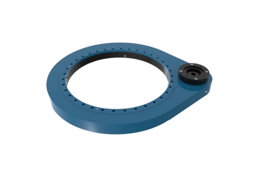
When the application requires an enclosed drive rather than an exposed ring gear, a Slew Drive may be a better layout choice. The decision still depends on torque, positioning needs, available space, and whether the equipment needs the bearing ring to be installed around an inaccessible center section.
Luoyang Slewring Bearing Co., Ltd. supports bearing selection from concept sketches through detailed design review. Our facility is ISO 9001:2015 certified, and every slewing bearing passes CMM three-coordinate inspection and dynamic load testing under our stated quality process.
Request Your Custom Slew Drive or Bearing Spec
Tell us your load, speed, and environment — receive a tailored 100–5000 mm slewing drive or slewing bearing proposal with 3D drawings within 24 hours.
Use this concept-stage procedure before specifying either architecture
The best time to choose between sectional and continuous rings is before the machine frame is finalized. The following process gives procurement teams and design engineers a clear basis for an RFQ rather than asking a supplier to guess from a bearing diameter alone.
- Map the assembly sequence. Draw the order in which the shaft, hub, gearbox, frame, bearing, and rotating upper structure are installed. Identify any part that prevents a full ring from reaching its final position.
- Confirm service access. Determine whether the bearing must be replaced in the field and what components would need removal. Include access for lifting equipment, fastener tools, measuring devices, and safe handling of each bearing section.
- Define the load case. Provide axial force, radial force, overturning moment, operating positions, rotation range, duty cycle, and peak versus normal working conditions. Do not submit only the machine weight.
- Assess mounting structure. Document inner and outer mounting diameters, flange thickness, support continuity, bolt pattern, and available machining surfaces. The bearing supplier needs this information to assess local support near the joints.
- Review drive arrangement. State whether the system uses a pinion, worm drive, hydraulic motor, electric motor, or manual rotation. For geared rings, include gear position and the required rotation range.
- Set the environmental requirement. Describe corrosion exposure, contaminants, temperature conditions, moisture, and maintenance access. Material selection should match the working condition rather than follow a default preference.
- Request an engineering proposal. Ask for drawings, load confirmation requirements, mounting guidance, inspection scope, and any limitations that apply to the selected architecture.
Do not make the common mistake of treating bearing outside diameter as the main selection value. Two rings with similar diameters can face very different overturning moments, mounting stiffness, rotational accuracy, and installation access requirements.
Avoid selection errors that turn an access solution into a service problem
Most errors happen when the team focuses only on whether the ring can be physically installed. That question matters, but it must be paired with a load and mounting review.
- Mistake: choosing sections because the center shaft looks inconvenient.
Check whether the shaft is truly permanent or whether a planned assembly sequence would allow a one-piece ring. A split design is best when it removes a real disassembly barrier, not a minor inconvenience. - Mistake: sending only dimensions for quotation.
Dimensions define package space, but they do not define load capacity or joint suitability. Include loads, duty cycle, rotation range, mounting details, and environmental conditions. - Mistake: assuming all loads are vertical.
Offset equipment creates radial forces and overturning moment. These loads often control slewing-bearing selection more strongly than static weight alone. - Mistake: overlooking fastener access.
Sections may fit around a shaft while bolt heads, nuts, or tightening tools remain inaccessible. Confirm the full installation procedure with the actual machine geometry. - Mistake: separating bearing and drive decisions.
A ring gear, pinion, and drive mounting arrangement influence each other. Where positioning and rotation are provided by an enclosed worm system, review a Worm Gear Slew Drive as part of the total layout. - Mistake: treating a custom ring as a standard catalog item.
When joint positions, bolt patterns, gear teeth, materials, or protective features differ from standard products, the supplier should review the application before production.
For custom projects, Luoyang Slewring Bearing Co., Ltd. offers a technical proposal within 24 hours and a 3-day rapid prototyping service. Standard product MOQ starts at one set, while customized product MOQ starts at five sets, which can help equipment builders validate the architecture before a larger release.
Apply the decision to real equipment layouts
Consider a rotating platform built around a large fixed center column. If the column cannot be removed after the base frame is welded, a one-piece ring may require the bearing to be installed much earlier in production. That can complicate painting, transport, later assembly, and service replacement.
In that situation, a split arrangement may be justified because it allows installation around the fixed column. The engineering review should then focus on the mounting surface around each section, the location of the joints relative to the platform load path, and whether installers can reach every mounting bolt.
Now consider a new machine where the base frame, center shaft, and upper assembly are all built in a controlled production sequence. If the bearing can be placed over the shaft before final closure, a continuous ring is usually the more direct choice. There is no need to add sectional interfaces when the production sequence already provides open access.
For very high-duty applications, the rolling-element arrangement should also match the load case. Engineers comparing alternatives can review Three-row Roller Slewing Bearings where separate raceway paths may be relevant to the application load pattern. The final selection still requires actual load data and mounting details.
Luoyang Slewring Bearing Co., Ltd. has supported more than 2,000 heavy-equipment projects across slew bearing and slew drive applications. Our engineering team can review custom ring architecture, material choices, gear requirements, and manufacturing feasibility for construction machinery, port equipment, industrial automation, and other rotating systems.
The engineering conclusion is straightforward. Specify a sectional ring when a fixed center component, restricted installation path, or field-service requirement makes a continuous ring impractical, and when the joint arrangement can be verified against the actual load and mounting conditions. Specify a one-piece ring when assembly access is available and there is no strong service or layout reason to divide the ring.
Request Your Custom Slew Drive or Bearing Spec
Tell us your load, speed, and environment — receive a tailored 100–5000 mm slewing drive or slewing bearing proposal with 3D drawings within 24 hours.
 WhatsApp

 +8613903880726