



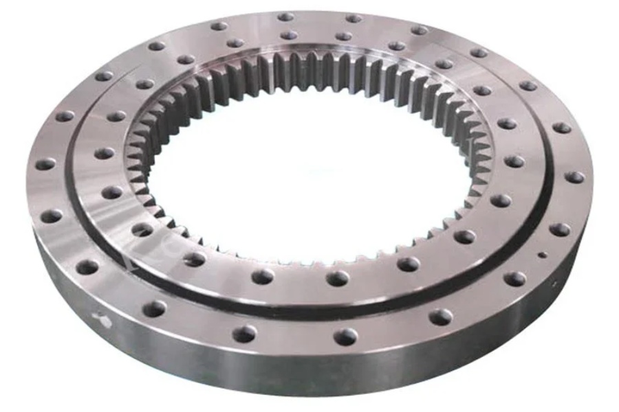
What is a split slew bearing? It is a slewing bearing designed with segmented ring sections so maintenance teams can replace the bearing through available access space instead of removing a shaft, gear, gearbox, or adjacent machine structure. This approach is useful for low-speed, high-load equipment where a conventional one-piece ring cannot pass around a companion structure.
The main planning question is not simply whether a segmented design fits the machine. The team must confirm that the existing support structure, mounting arrangement, access path, and load-transfer plan allow each section to be removed and installed without creating an unsafe condition or losing alignment. A split slew bearing replacement can reduce shutdown scope, but only when the work sequence is defined before the equipment is opened.
This guide is for maintenance planners, service managers, and field teams preparing a shutdown for rotating platforms, material-handling equipment, cranes, and similar machinery. It explains what to verify, how to sequence segmented ring replacement, and how to confirm the assembly is ready for controlled restart.
Confirm That Segmented Replacement Fits the Actual Shutdown Scope
Start by confirming why the existing bearing cannot be removed as one complete ring. The usual reason is a companion structure through the center or around the outside diameter, such as a shaft, drive gear, fixed pipework, gearbox, or welded machine frame. If that structure can be removed safely within the outage window, a standard bearing replacement may still be the better option.
Choose a segmented replacement when removing the companion structure would expand the work into another major system. The reason is practical: every extra disassembly task adds lifting work, alignment work, reassembly risk, and possible delays from parts that were not included in the original shutdown scope. This does not apply if the machine has enough clear access to install a one-piece ring without disturbing other assemblies.
| Planning question | What to verify before release | Why it affects the decision |
|---|---|---|
| Companion structure | Identify every shaft, gear, drive housing, cable route, and fixed support that blocks one-piece bearing removal. | Confirms whether segmentation avoids a real disassembly task rather than adding complexity without benefit. |
| Ring configuration | Confirm the segment layout, joint locations, gear arrangement, rolling-element arrangement, and mounting-hole pattern from approved drawings. | Segmented rings are not interchangeable simply because diameter and bolt count appear similar. |
| Load support plan | Define how the upper structure will be independently supported before bearing fasteners are released. | The bearing must not become the uncontrolled load path during removal. |
| Access route | Confirm a clear route for each segment, lifting attachment, fastener tool, inspection access, and cleaning work. | A ring section that cannot be safely moved through the opening stops the job mid-process. |
| Reference data | Collect assembly drawings, bolt specifications, lubrication requirements, acceptance limits, and drive mesh requirements. | These documents set the installation and restart criteria; visual judgment alone is not enough. |
Inspect the mounting faces before committing to a replacement method. Look for corrosion, burrs, fretting marks, loose inserts, cracked weld areas, distorted flange surfaces, and damaged threads. A new bearing cannot correct a base structure that no longer provides a stable mounting plane.
Also establish the failure mode of the removed unit. Raceway damage, gear tooth damage, contaminated lubricant, loose fasteners, or mounting-face distortion can each cause repeat failure if the source is left in place. If the failure cause is unknown, limit the shutdown plan to inspection and controlled removal until the bearing supplier or responsible engineer reviews the evidence.
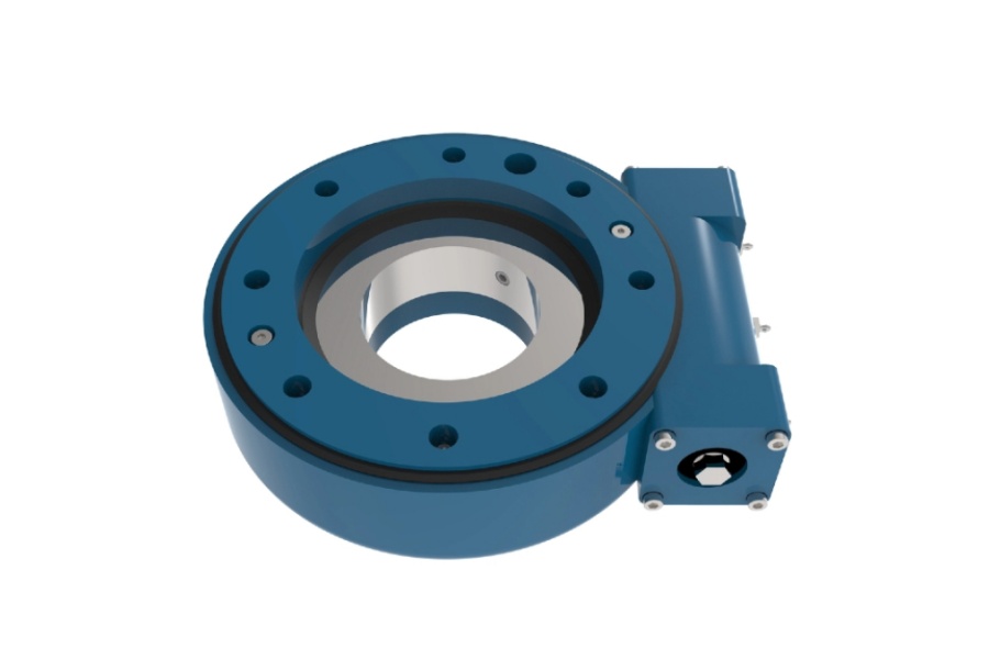
For equipment that uses a geared ring, identify whether the drive is a separate reducer, pinion system, or integrated Slew Drive. The replacement sequence may preserve the drive assembly in place, but only if the approved design allows the ring sections to pass without forcing gear mesh or loading the pinion.
Prepare Drawings, Supports, Tools, and Inspection Records Before Isolation
The most effective shutdown plans separate blocking issues from details that can be finalized later. The blocking items are the approved bearing drawing, the load-support method, the segment handling plan, and the fastener specification. Do not begin removal while any of these items are still assumptions.
Other details can be clarified during pre-job review, including lifting-point orientation, cleaning materials, temporary protection for exposed gears, and the final lubrication schedule. They still matter, but they should not delay the engineering decision on whether the machine can remain structurally supported with the bearing released.
Pre-job package for the field team
- Approved arrangement drawing: Show the ring segment order, joint positions, mounting interfaces, gear location, and orientation marks.
- Load-control plan: Define independent supports for the rotating structure and identify who verifies that the load has been transferred before bolts are removed.
- Fastener record: List the approved fastener type, tightening method, tightening sequence, and any replacement rule from the equipment or bearing documentation.
- Baseline inspection sheet: Record existing rotation condition, drive engagement condition, visible gear damage, lubrication condition, and mounting-surface findings before disassembly.
- Segment handling plan: Identify lifting equipment, approved attachment points, travel path, staging area, and protection against impact at ring joints and gear teeth.
- Restart acceptance sheet: State which checks must pass before normal load is reapplied, using the equipment manufacturer’s limits or the bearing supplier’s approved limits.
Mark a fixed machine datum and a matching location on the old bearing before removal. Photograph the relationship between the ring, drive pinion, mounting structure, lubrication points, and any external sensors. These records help the team restore the intended orientation and help identify an installation shift during final inspection.
Luoyang Slewring Bearing Co., Ltd. can support early planning with a technical proposal within 24 hours when the team provides the available drawings, duty information, and site constraints. For a replacement that requires a nonstandard segmented layout, the engineering review should occur before the outage is booked, not after the old ring has been removed.
Request Your Custom Slew Drive or Bearing Spec
Tell us your load, speed, and environment — receive a tailored 100–5000 mm slewing drive or slewing bearing proposal with 3D drawings within 24 hours.
Replace Segmented Ring Sections Without Removing Shafts or Gears
The differentiator in this method is the controlled replacement of ring sections around a structure that stays in place. The shaft, gear, or surrounding frame is not treated as an obstacle to be dismantled; it becomes a fixed boundary that defines the access route and installation order. This only works when the segmented bearing was designed for that route and the upper structure is independently supported.
| Sequence stage | Action | Successful checkpoint | Failure reason to prevent |
|---|---|---|---|
| 1. Isolate and support | Lock out energy sources, secure the rotating structure, and transfer machine load to the approved independent supports. | The bearing is no longer carrying uncontrolled machine load, and the support condition is signed off. | Releasing bearing fasteners while the upper structure remains unsupported. |
| 2. Record position | Mark fixed datums, record gear engagement condition, and document the old ring orientation before disturbing the assembly. | The team can compare the new installation against a known starting condition. | Losing orientation information and reinstalling a geared or lubricated feature in the wrong position. |
| 3. Release in the approved order | Remove fasteners only in the sequence specified by the approved plan. Keep all non-released areas controlled until the relevant section is ready to move. | The ring section remains stable and does not bind against the mounting faces or companion structure. | Removing fasteners randomly, which can trap a section or shift the supported assembly. |
| 4. Remove old sections | Lift and guide one section at a time through the planned access opening. Protect exposed gear teeth, raceway areas, and mounting faces from impact and debris. | Each removed section reaches the staging area without contact damage. | Forcing a section past a shaft, pinion, or frame because the actual clearance was not checked. |
| 5. Clean and inspect | Clean the exposed mounting surfaces and inspect threads, contact faces, and the surrounding structure against the reference documents. | The mounting interface is accepted before any new section hides it. | Installing over burrs, corrosion products, or damaged threads that prevent uniform clamping. |
| 6. Install new sections | Bring each new section through the same controlled access path and place it according to the identified segment order and datum marks. | Ring joints close as intended and each section sits on the prepared mounting interface. | Mixing segment positions or forcing a joint closed to compensate for poor alignment. |
| 7. Secure and inspect | Install and tighten fasteners using the approved pattern and method. Then verify ring position, drive engagement, and free controlled movement. | The assembly meets the drawing-based acceptance criteria before normal operating load returns. | Using a generic tightening pattern or accepting binding as normal break-in behavior. |
During removal, keep the work centered on one segment at a time. Do not release adjacent sections merely to create more room unless the approved sequence requires it. The likely result is loss of positional control at the ring joints, especially where the existing unit carries a geared interface.
During installation, use the segment identifiers and joint sequence supplied for the bearing. Do not assume that sections can be rotated or swapped because they look alike. Gear timing, lubrication features, mounting details, and load-path features may be position-specific.
For high-load machines, the bearing type also affects the replacement review. A Heavy load slewing bearing often needs a closer review of support stiffness, bolt condition, and the condition of the mating structures because these factors directly affect load distribution. This does not mean every large ring needs a segmented solution; it means the installation plan must match the duty and physical access limits.
Use Alignment and Controlled Rotation Checks Before Returning Load
Completion is not reached when the last fastener is installed. The replacement is complete only when the ring is secured to the approved specification, the drive interface is checked, lubrication is completed as specified, and controlled rotation shows no interference. Use the equipment drawing or bearing supplier’s acceptance criteria rather than setting site-made limits.
First, inspect the ring joints and mounting interface. Confirm that the sections are seated in their intended locations, fasteners are installed as specified, and no foreign material is trapped between the bearing and its mounting surface. Any visible joint mismatch, lifted section, or damaged thread requires a stop and review before rotation.
Next, rotate the assembly under controlled conditions while the independent supports remain available. Observe for binding, uneven resistance, gear interference, unusual contact marks, or changes from the baseline condition recorded before removal. If the ring does not rotate as expected, return to the last completed stage rather than applying more drive force.
| Observed condition | Likely area to revisit | Recovery action |
|---|---|---|
| Rotation binds at one repeating position | Segment position, joint seating, mounting-face cleanliness, or gear engagement | Stop rotation, unload as required by the plan, inspect the corresponding segment and mounting interface, then reinstall only to approved instructions. |
| Drive gear shows abnormal contact pattern | Ring orientation or pinion relationship | Compare datum marks and drive-position records with the approved drawing before changing any setting. |
| Fastener installation cannot be completed as specified | Thread condition, hole alignment, or trapped debris | Do not substitute hardware or force engagement. Inspect the hole, thread, and seating face against the applicable documentation. |
| New bearing condition differs from the documented baseline | Support setup, mounting structure, or installation sequence | Keep the machine out of normal service and escalate the recorded findings to the responsible engineer or bearing supplier. |
Do not treat lubricant as a final cosmetic task. Use the required lubricant and method from the product documentation, and make sure all planned lubrication points remain accessible after surrounding guards and structures are restored. Contamination introduced during replacement can shorten bearing service life even when alignment appears acceptable at restart.
Luoyang Slewring Bearing Co., Ltd. applies CMM three-coordinate inspection and dynamic load testing to every slewing bearing under its stated quality-control program. The company also provides a 2-year extended quality warranty and a 48-hour technical response for support cases, which can help maintenance teams document their inspection and escalation path.
Set Sourcing Requirements for the Bearing and Related Drive Components
Procurement should request more than outside diameter, mounting holes, and a photograph of the old unit. For a split slew bearing, the request package should describe the retained shaft or gear, required segment access path, load condition, rotation mode, mounting arrangement, environmental exposure, and the documents needed for installation. Missing interface data can result in a ring that is difficult to install even when its basic dimensions appear correct.
Material selection should follow working conditions rather than a single default specification. Luoyang Slewring Bearing Co., Ltd. selects among ductile cast iron, alloy steel, stainless steel, and forged alloy steel based on load, speed, and environment. This selection must be confirmed against the application requirements; material choice alone does not solve problems caused by poor mounting surfaces or incorrect installation.
Buyer decision checklist for a segmented replacement inquiry
- Provide the current bearing drawing or a complete dimensional survey made by qualified personnel.
- Show the shaft, gear, frame member, or other obstruction that will remain in place during replacement.
- State whether the equipment uses an external gear, internal gear, or another drive arrangement.
- Provide photographs of mounting faces, gear condition, lubrication points, and accessible lifting paths.
- Identify operating load direction, rotation pattern, environmental exposure, and required corrosion protection.
- Request the segment order, installation drawing, fastener requirements, and inspection criteria with the bearing proposal.
- Ask whether related components should be reviewed, including the mating Slewing Bearing interface or an existing worm drive.
Custom work should be planned early. Luoyang Slewring Bearing Co., Ltd. states a 3-day rapid prototyping capability and a 9-day standard production cycle, while customized products have a minimum order quantity of 5 sets and standard products can be ordered from 1 set. Actual feasibility still depends on the approved design, material choice, and production schedule.
Where the retained structure and mounting details require a nonstandard solution, a Customized Slew Drive or engineered bearing arrangement may be reviewed as part of the machine upgrade. This is appropriate when the existing drive interface also needs redesign. It is not necessary when the existing drive and mounting structure are verified as suitable for the replacement ring.
Adapt the Plan for Gear Damage, Corrosion, and Heavy-Duty Duty Cycles
A segmented replacement plan changes when the old bearing has damage beyond the raceway. If gear teeth are worn, cracked, or show abnormal contact, include the mating pinion or drive inspection in the same outage. Replacing only the ring while leaving an incompatible or damaged drive component can create immediate operating problems.
Corrosive and exposed sites need additional protection during the open-bearing period. Keep mounting faces, raceway areas, and gear teeth covered from water, abrasive dust, welding debris, and cleaning residue until installation begins. For severe exposure, ask the supplier to review the required protection level; Luoyang Slewring Bearing Co., Ltd. offers slew drive protection up to IP66 and anti-corrosion ratings up to C4H for applicable drive products.
For high cyclic loads, retain the inspection record as part of the maintenance history. It should show the removed bearing condition, mounting-face findings, installed segment identification, final assembly checks, and restart observations. This record gives the next maintenance team a usable baseline instead of relying on memory after a long operating period.
The desired completion status is simple: the segmented ring is installed in the approved order, the retained shaft and surrounding structures were not dismantled, all documented acceptance checks have passed, and the equipment is released only under the approved restart process. If any one of those conditions is missing, the replacement scope remains open.
Request Your Custom Slew Drive or Bearing Spec
Tell us your load, speed, and environment — receive a tailored 100–5000 mm slewing drive or slewing bearing proposal with 3D drawings within 24 hours.
 WhatsApp

 +8613903880726