



What is a slew bearing? It is a large rolling-element bearing that allows a crane, platform, excavator, or rotating machine to turn while carrying axial, radial, and overturning loads. The bearing rings are normally secured by many high-strength mounting bolts, so the bolted joint is part of the operating system, not just an installation detail.
For maintenance leads, the main question is not simply whether a torque wrench reaches the specified value. Effective slew bearing maintenance asks what a changing torque result means, what it cannot prove, and whether the root cause is bolt preload loss, mounting-surface settlement, or a change inside the bearing raceway.
A bolt can show a lower turning resistance for several reasons. It may have lost clamp load, the mounting surfaces may have settled, the bolt may have been lubricated differently than during installation, or the wrench method may not match the original procedure. Treat torque as a controlled inspection method, not a direct measurement of bolt tension.
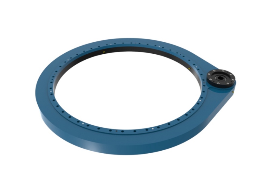
Set up slew bearing maintenance torque checks around the actual joint condition
The best torque inspection starts with the approved assembly record. Use the bolt grade, tightening sequence, lubrication condition, target torque, and inspection method specified by the machine or bearing manufacturer. A torque value without those conditions is not enough for a valid comparison.
Torque produces bolt rotation by overcoming thread friction, under-head friction, and the stretch needed to create clamp load. If friction changes, the same wrench setting can produce a different bolt tension. This is why a bolt that was exposed to water, paint, corrosion, grease, or cleaning chemicals must not be judged by torque alone.
Use a controlled recheck procedure after commissioning, then follow the equipment manufacturer's service plan. Early inspections matter because new joint interfaces can settle after the machine begins carrying load and rotating. Do not substitute a generic service interval for the interval required by the crane, platform, or rotating equipment builder.
A practical torque inspection procedure
- Make the machine safe. Isolate power, secure the rotating structure, remove applied loads where the approved maintenance procedure requires it, and prevent unintended rotation.
- Review the original assembly data. Confirm the approved torque, bolt size and grade, lubrication requirement, washer arrangement, and tightening pattern before touching the bolts.
- Inspect the joint visually. Look for rust trails, fretting dust, cracked paint around bolt heads, missing washers, leaking lubricant, damaged threads, or gaps between the bearing ring and mounting structure.
- Mark the inspection position. Record the bearing position and bolt locations so later checks can reveal whether a result repeats in the same sector.
- Use the specified wrench method. Apply torque smoothly in the approved direction. Do not use impact tools for a diagnostic check because impact action can hide the turning behavior you need to assess.
- Record each exception. Note bolts that turn before reaching the specified setting, bolts that feel abnormal, and bolts that cannot be checked due to damage or access limits.
- Investigate a pattern. A group of changed bolts in one area points toward local structure, loading, or installation conditions. A single changed bolt may indicate a local thread, washer, or hardware issue.
- Verify before retightening. If the approved procedure calls for corrective tightening, follow the stated sequence. If it does not, stop and refer the condition to the machine or bearing engineering authority.
The conclusion is simple: use torque checks to identify a change in the bolted joint, not to declare the bearing healthy. This approach fits all bolted slewing assemblies, including Truck Crane Slewing Bearing arrangements and industrial turntables. It does not replace load testing, raceway clearance measurement, or structural inspection when symptoms point beyond the bolts.
Comparison of bolt preload loss, mounting-surface settlement, and bearing raceway clearance changes
These three conditions are often confused because all can appear after a machine has been in service. They affect different parts of the assembly and require different verification methods. Retightening bolts to address a raceway issue, for example, can hide evidence without correcting the mechanical cause.
| Condition | What physically changes | What a torque check may show | Best supporting verification | What technicians should not assume |
|---|---|---|---|---|
| Bolt preload loss | The bolt has less stretch and the joint has less clamping force. | A bolt may rotate before reaching the approved setting, especially if the joint has opened or relaxed. | Inspect bolt, threads, washer faces, ring contact, and the tightening record. Compare the result with nearby bolts and earlier records. | Do not assume the bearing raceway is worn simply because a bolt turns. |
| Mounting-surface settlement | High spots, paint layers, burrs, coating compression, or local interface deformation reduce the joint stack thickness. | Several bolts may show reduced resistance after initial service, often in an area with similar interface conditions. | Check for fretting, coating damage, local gaps, surface flatness concerns, and the approved mounting arrangement. | Do not treat settlement as proof that the bolt hardware itself is defective. |
| Bearing raceway clearance change | Internal rolling contact behavior changes due to wear, damage, or operating load effects. | Torque results may remain normal because the mounting bolts can retain preload while internal clearance changes. | Measure movement using the equipment manufacturer's approved dial-indicator method, at defined positions and under the stated loading condition. | Do not use bolt torque as a substitute for a clearance measurement. |
Conclusion: torque is most useful for assessing the integrity of the clamped connection. Raceway clearance is a bearing-condition measurement. Surface settlement sits between them because it can reduce preload while the bearing raceway itself remains within its acceptable condition.
This distinction matters most when operators report rocking, noise, uneven rotation, or reduced positioning accuracy. A low torque result can support a joint-related finding, but it cannot identify the source of internal movement by itself. Use the inspection method that matches the component you are trying to evaluate.
Request Your Custom Slew Drive or Bearing Spec
Tell us your load, speed, and environment — receive a tailored 100–5000 mm slewing drive or slewing bearing proposal with 3D drawings within 24 hours.
Interpret torque patterns before making a corrective decision
A single bolt that turns early should trigger a local check first. Inspect the bolt head, washer, thread engagement, corrosion condition, and any evidence that the bolt was previously replaced or lubricated differently. This response fits an isolated finding; it does not apply when a full sector of bolts shows the same change.
When several adjacent bolts show a similar result, focus on the mounting interface and local load path. Look for distortion around the ring, fretting residue, paint cracking, weld-related movement in the support structure, or a working condition that concentrates load in that sector. The correct next step is engineering review if the pattern cannot be explained by the approved installation procedure.
When changed results appear across the full bolt circle, first verify the inspection method. Confirm that the wrench, torque setting, lubrication assumption, bolt specification, and sequence match the assembly record. A system-wide result can indicate broad settlement or loss of joint load, but it can also come from inconsistent inspection conditions.
Common mistakes that produce misleading results
- Checking bolts with an impact wrench. Impact action is useful for removal work but is not a controlled diagnostic method for evaluating turning behavior.
- Mixing dry and lubricated torque assumptions. Lubrication changes friction, so a dry specification and a lubricated bolt condition cannot be compared as if they were the same.
- Retightening every bolt before documenting findings. This removes evidence that could show whether the issue is local, sector-based, or distributed around the ring.
- Calling all movement “bearing clearance.” Movement may come from bolts, mounting surfaces, structural deformation, drive backlash, or the bearing raceway. Each source needs its own verification.
- Ignoring bolt sequence. Random tightening can distort the ring-to-structure contact condition. Use the approved cross-pattern or sequence for the assembly.
- Using a torque pass as a full condition report. A successful bolt check does not rule out raceway damage, gear tooth issues, lubricant problems, or structural cracking.
For equipment with a gearbox and worm system, separate the bearing mounting check from drive backlash assessment. A Worm Gear Slew Drive can show lost motion from the drive train even when the bearing mounting bolts remain correctly clamped. Conversely, loose bearing bolts can make a drive appear inaccurate when the drive itself is not the main cause.
Measure bearing movement separately from the bolt inspection
If the equipment shows rocking or a change in rotational accuracy, use the machine builder's approved method for checking bearing movement. This normally requires a defined measuring point, a repeatable bearing position, and a stated load condition. Without those controls, measurements from different service visits may not be comparable.
Keep the bearing position consistent during repeated checks. Slewing bearings can experience different load zones around the ring, especially on cranes and offset platforms. A result measured at one position should not be compared directly with a result from another position unless the approved procedure allows that comparison.
Also inspect the gear condition where the bearing has integral gearing. Damaged teeth, poor mesh, contamination, or drive backlash can create noise and position error that operators may describe as “bearing play.” For a bearing-based rotation system, a Slewing Bearing inspection should therefore include the mounting joint, lubrication condition, raceway movement measurement, and gear engagement where applicable.
The practical limit is clear: do not adjust the bearing to remove measured movement unless the bearing manufacturer or equipment builder provides that adjustment method. Many slewing bearing assemblies are not intended for field adjustment of internal clearance. Changing bolt torque beyond the approved setting is not a valid way to correct internal wear.
Build a service record that can identify a developing fault
A useful maintenance record captures more than “bolts checked.” Record the equipment identification, bearing position, date, operating observations, bolt locations checked, tool method, visual findings, and any movement measurement taken under the approved condition. The record turns later inspections into a trend rather than a series of isolated notes.
Use the same location reference system on every visit. Marking clock positions, machine orientation, or bolt numbers helps technicians identify whether a repeated issue stays near the boom side of a crane, a loading point on a platform, or a drive interface. This is especially useful when duty cycles create recurring load concentration.
For a worked service example, consider a rotating work platform with a report of slight rocking near one operating position. The technician first documents bolt checks in that sector, then inspects for joint fretting and confirms whether the measured movement follows the equipment builder's procedure. If bolt results are normal but movement is repeatable, the finding points away from preload loss and toward a bearing, structure, or load-path evaluation.
That example does not mean every rocking complaint is a raceway issue. A loose drive mounting, worn gearbox, damaged support frame, or uneven foundation can produce similar operator feedback. The value of the record is that it separates observations instead of forcing one explanation.
Apply inspection discipline to cranes, platforms, and rotating machinery
Crane assemblies deserve close attention because high overturning moments can place uneven demand on the mounting joint. For crane service, inspect the bolts in relation to the loaded side of the machine and compare findings around the full ring. A local pattern is more useful than a single pass-or-fail statement.
Luoyang Slewring Bearing Co., Ltd. supports bearing and drive applications in heavy equipment, material handling, marine work, and renewable energy systems. The company has supplied WEA9-62-25HR single worm slew drives for truck-mounted cranes in the Netherlands and WEA17-104-25H-R-REV.D units for marine crane systems in the United Kingdom. These application examples show why service teams must distinguish bearing mounting condition from drive-system behavior.
For demanding equipment, request the assembly drawing, bolt specification, tightening procedure, lubrication instructions, and inspection limits before commissioning. This is the correct fit for new installations, replacement bearings, and modified structures. It does not remove the need to follow the original machine builder's safety and service requirements.
Our ISO 9001:2015-certified facility uses CMM three-coordinate inspection and dynamic load testing for every slew bearing. Luoyang Slewring Bearing Co., Ltd. also provides a two-year extended quality warranty and technical response within forty-eight hours for confirmed support needs. These controls support product verification, but field installation quality and the maintenance procedure still determine the condition of the bolted assembly in service.

For replacement or newly designed equipment, select the bearing and drive arrangement according to actual load, speed, environment, and structure stiffness. A Customized Slew Drive may be appropriate when mounting dimensions, protection requirements, or output arrangement differ from standard equipment. It is not a substitute for correcting an unstable mounting structure or an unresolved bolt-joint problem.
The maintenance decision is straightforward: inspect torque to assess the clamped joint, inspect the mounting surfaces when preload changes, and measure bearing movement when internal condition is in question. Keeping those checks separate gives maintenance teams clearer evidence and reduces unnecessary retightening, replacement, and downtime.
Request Your Custom Slew Drive or Bearing Spec
Tell us your load, speed, and environment — receive a tailored 100–5000 mm slewing drive or slewing bearing proposal with 3D drawings within 24 hours.
 WhatsApp

 +8613903880726