



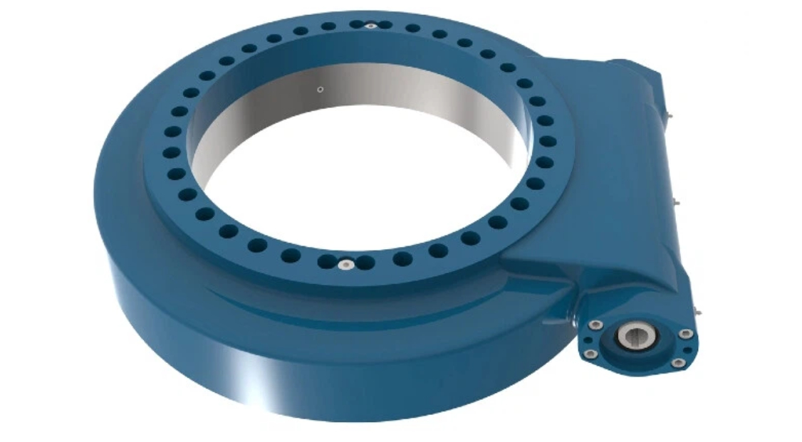
What is a slewing ring? A slewing ring is a large-diameter rolling bearing that supports rotation while carrying axial load, radial load, overturning moment, or a combination of these forces. It is commonly used in cranes, excavators, turntables, solar trackers, marine equipment, and industrial positioning systems.
The purpose of a slewing ring inspection before a planned shutdown is not simply to find visible marks. The real task is to determine whether the raceway evidence indicates normal running-in, localized overload damage, contamination damage, corrosion, or a condition that may affect safe operation before the next service interval.
Start with a clean bearing, a known rotation direction, and a record of where each observation occurs. Raceway wear cannot be judged reliably from one damaged-looking area alone. The location, pattern, depth, repeatability, lubrication condition, and measured movement all affect the maintenance decision.
Start with a clean access plan and establish a repeatable baseline
A useful inspection begins before the ring is opened or removed. Review operating symptoms reported by the machine team, including noise during rotation, increased drive torque, uneven movement, grease leakage, vibration, reduced positioning accuracy, or a change in backlash. These symptoms do not prove raceway damage, but they help direct the inspection toward the most heavily loaded zones.
Mark the ring’s position relative to the machine structure before rotation testing. This allows the inspector to connect a defect with a boom position, a parked position, a recurring load direction, or a fixed gear location. A defect that always appears at the same machine angle usually has a different cause from wear spread evenly around the full circumference.
Remove old grease and contamination from accessible areas without scratching the raceway surface. Examine seals at the same time. A torn, hardened, displaced, or leaking seal can allow water, dust, abrasive particles, and degraded grease into the bearing, which can change a small surface mark into a wider damage pattern.
Use strong directional light, a clean lint-free wipe, and close visual access. A borescope may be useful where the raceway cannot be viewed directly, but its images should be compared with movement and clearance measurements. A camera image without position marking is much less useful for a shutdown decision.
Record these details for every suspect area
- Ring position: identify the machine angle or clock position where the mark appears.
- Raceway location: note whether the condition is on the inner ring or outer ring, and whether it is near a loaded zone.
- Contact pattern: record whether the mark is smooth, rough, cratered, indented, stained, flaking, or raised at the edges.
- Grease condition: look for metal particles, water discoloration, hard contamination, or loss of grease film.
- Seal and bolt condition: inspect for seal damage, loose fasteners, fretting around mounting faces, or evidence of ring movement.
- Operational symptom: connect the observed area to noise, resistance, vibration, or loss of accuracy during rotation.
The conclusion at this stage should be limited: identify where evidence exists and whether it appears localized or distributed. Do not declare a bearing serviceable merely because the exposed portion of the raceway looks smooth. Hidden loaded zones and mounting problems may still require further checks.
For machines using a large Heavy load slewing bearing, documenting the loaded sector is especially useful because overturning moment can concentrate contact stress in only part of the ring. The same practice applies to crane and excavator applications where repeated work cycles favor certain boom or upper-structure positions.
Compare normal polishing, pitting, brinelling, and corrosion by observable raceway evidence
The most common inspection error is treating every shiny or discolored track as a failure. Some polished contact paths are expected after normal rolling contact. The decision changes when the surface contains depressions, broken edges, repeated indentations, rust attack, or evidence that the rolling elements are no longer supported by a continuous smooth path.
| Observed condition | What the raceway usually looks like | Likely practical effect | Best next check | When the visual sign alone is not enough |
|---|---|---|---|---|
| Normal polishing | A smooth, bright, continuous track with no broken edges, loose material, or distinct depressions. | Often indicates normal rolling contact and grease displacement along the loaded path. | Confirm smooth rotation, adequate grease condition, seal condition, and stable measured movement. | Polishing is not automatically acceptable if it occurs with unusual noise, rising backlash, or mounting-face movement. |
| Pitting | Small cavities, pinholes, rough crater-like areas, or localized surface breakup. Edges may feel sharp or uneven. | Interrupts rolling contact, can generate debris, and may spread as rolling elements pass over damaged material. | Check grease for metallic debris, map the area, and compare movement through the affected sector. | Surface staining can resemble pitting in poor light. Clean and inspect at different light angles before judging depth. |
| Brinelling | Repeated dents or indentations that follow the spacing of rolling elements, often concentrated in a parked or heavily loaded position. | Can produce a repeating vibration, clicking feel, or resistance as rolling elements cross the indented zone. | Rotate slowly through the location and compare resistance with other positions. Review shock loads and prolonged static loading. | Do not confuse brinelling with random impact marks or contamination dents. The repeated spacing pattern is the key evidence. |
| Corrosion | Red-brown discoloration, black oxidation, etched areas, rust lines, or rough patches near damaged seals and water entry paths. | Creates abrasive particles, damages surface finish, and can lead to pitting if moisture remains in the raceway. | Inspect seals, grease condition, drainage, storage practices, and exposed mounting areas for moisture paths. | Color alone does not define severity. A light stain may wipe away, while etched corrosion remains rough after cleaning. |
Normal polishing fits a bearing that rotates smoothly, retains clean grease, and shows no measurable change in movement or operating behavior. It does not fit a ring with a polished band plus local flaking, raised ridges, or a recurring rough spot. The trade-off is simple: replacing a sound bearing wastes shutdown resources, while treating real surface breakup as harmless can allow damage to advance.
Pitting often calls for a more conservative decision than normal polishing because a pit is a loss of raceway material, not merely a change in color. The pattern matters. Widely scattered fine cavities may point toward moisture or contamination, while a concentrated damaged zone may be linked to a specific load position, lubrication issue, or mounting condition.
Brinelling should trigger a review of the machine’s duty cycle, parked position, impact events, and load-holding practice. It is most relevant when the equipment spends long periods under load without rotation or experiences sudden shock. It does not automatically mean that the entire bearing is damaged around the full ring.
Corrosion requires both surface assessment and cause control. Re-greasing a corroded raceway without correcting seal damage or water entry may only delay a repeat problem. For outdoor equipment, inspect the housing interfaces and grease points as carefully as the visible raceway.
Luoyang Slewring Bearing Co., Ltd. selects bearing materials according to load, speed, and operating environment, including ductile cast iron, alloy steel, stainless steel, and forged alloy steel where applicable. Material selection can improve suitability for a service condition, but it does not remove the need for correct sealing, lubrication, mounting support, and inspection.
Request Your Custom Slew Drive or Bearing Spec
Tell us your load, speed, and environment — receive a tailored 100–5000 mm slewing drive or slewing bearing proposal with 3D drawings within 24 hours.
Confirm visual findings with movement, mounting, and lubrication checks
Visual evidence should be confirmed with mechanical evidence before deciding whether to monitor, repair, or replace the ring. A dial indicator can help compare movement at several ring positions under a controlled load condition. The useful result is the pattern of change around the ring, not a single reading viewed without a baseline.
Place the indicator at a stable reference point and apply the same practical loading method at each marked position. Record axial and radial movement separately where the machine design allows it. If one sector shows a clear increase compared with nearby sectors, inspect that sector again for raceway damage, bolt issues, structural distortion, or gear engagement problems.
Increased movement does not always come from the raceway. Loose mounting bolts, damaged bolt threads, fretting between the ring and mounting face, distorted support structures, and gear tooth wear can create similar symptoms. This is why a bearing should not be removed solely because the machine has backlash.
Use this confirmation sequence before authorizing major work
- Clean and photograph the accessible raceway, seals, grease ports, and mounting areas.
- Mark the rotation position of every suspect area and connect it to the machine’s working orientation.
- Rotate slowly through a full operating range while checking for roughness, noise, resistance, or a repeating click.
- Compare indicator movement at loaded and lightly loaded positions using the same fixture arrangement.
- Inspect mounting bolts and support surfaces for loosening, fretting, or signs that the ring has shifted.
- Check grease for contamination, moisture evidence, or metallic particles, then review seal condition.
- Decide whether the evidence supports monitoring, engineering review, controlled repair planning, or replacement.
This sequence is well suited to planned shutdown preparation because it separates an observable symptom from a verified condition. It does not replace the equipment manufacturer’s maintenance instructions, safety procedure, or load-handling requirements. If the machine is safety-sensitive, any finding that affects stability or controlled rotation should be reviewed by the responsible engineering authority.

Quality verification at the manufacturing stage also supports later maintenance decisions. Our ISO 9001:2015 certified facility uses CMM three-coordinate inspection and dynamic load testing for slewing bearings, while factory audit reports are available on request. Those controls confirm product quality at delivery; field inspection remains necessary because installation, loads, lubrication, seals, and environment determine in-service condition.
Decide between monitoring, repair planning, and replacement based on evidence
Monitoring is the reasonable choice when the raceway shows smooth polishing only, rotation remains consistent, grease is clean, seals are functional, and movement has no unusual localized change. This option fits a planned maintenance program with documented repeat checks. It does not fit a ring that has active material loss, repeated dents, or worsening symptoms.
Engineering review and repair planning may fit a localized defect when the root cause can be identified and the machine owner needs to evaluate downtime, risk, and remaining operating need. Raceway grinding or welding should never be treated as a routine field repair. Any proposed repair must account for bearing geometry, hardness condition, rolling contact path, and the effect on load distribution.
Replacement becomes the stronger option when pitting is spreading, brinelling creates repeated operating disturbance, corrosion has etched the contact surface, grease contains debris linked to raceway breakup, or movement and operational symptoms indicate loss of bearing condition. Replacement also makes sense when the cause cannot be corrected without restoring the bearing assembly and its mounting interfaces.
| Decision path | Evidence that supports it | What must happen next | What it should not be used for |
|---|---|---|---|
| Continue with monitoring | Smooth polishing, stable operation, clean grease, intact seals, and no localized change in movement. | Set a documented reinspection point and keep position-marked photos for comparison. | Known pitting, repeating dents, active corrosion, or unexplained operating symptoms. |
| Plan engineering review | Localized marks with uncertain cause, mixed inspection results, or possible mounting and structural effects. | Review load history, installation condition, fasteners, support stiffness, and lubrication practice. | A shortcut around a safety decision when damage is clearly progressing. |
| Plan replacement | Material loss, flaking, confirmed brinelling, etched corrosion, debris, or worsening movement and rotation behavior. | Confirm bearing drawing data, gear details, mounting interface, seal arrangement, and operating requirements. | Assuming the new ring alone will solve a load, alignment, or water-entry problem. |
When replacement is needed, the replacement specification must match the actual application rather than only the outside diameter. Buyers should provide the bearing drawing or dimensions, gear configuration, mounting hole pattern, load direction, rotation speed, lubrication arrangement, environmental exposure, and any required accuracy target. This information is also needed when considering a Customized Slew Drive for an integrated rotation system.
Luoyang Slewring Bearing Co., Ltd. supports standard product orders from one set and customized product orders from five sets. Sample orders are welcome for testing and evaluation. Standard production is listed as a nine-day cycle, while technical proposals can be provided within twenty-four hours when the required application information is available.
Prepare a shutdown evidence package that speeds up technical review
A good evidence package reduces delays between inspection and decision. It also prevents a supplier or engineering team from making assumptions from one unclear photograph. Include machine application details, ring identification data, photos with position marks, video of the rotation symptom if safe to obtain, indicator records, grease observations, and the maintenance history.
For a crane, capture the boom and upper-structure positions associated with the affected ring sector. For a solar tracker, record whether the defect corresponds to a repeated parking orientation, drive engagement point, or environmental exposure direction. For a turntable, identify whether the damaged sector matches a repeated loading station.
This approach has value across different equipment types. For example, Luoyang Slewring Bearing Co., Ltd. supplied WEA9-62-25HR single worm slew drives for port crane systems in a South Korean repeat order, with stated tracking precision of no more than 0.15 degrees, IP65 sealing, and self-locking function. A crane inspection for that type of system should assess both the rotating bearing condition and the drive-side behavior rather than treating them as separate symptoms.
For applications with a worm-driven rotation system, inspect the drive interface after confirming bearing condition. Excessive ring movement can affect gear engagement, while a drive problem can be mistaken for raceway damage. Review the matching Worm Gear Slew Drive arrangement when evaluating rotation resistance, backlash, and sealing as one system.
Buyer and maintenance checklist for a replacement inquiry
- Application type and machine function.
- Photos of the complete ring, damaged area, seals, gear, and mounting face.
- Ring drawing, part number, or measured interface details.
- Type of load and the positions where loading is repeated.
- Observed raceway condition: polishing, pitting, brinelling, corrosion, or mixed damage.
- Rotation symptoms, including roughness, noise, resistance, or uneven motion.
- Grease condition and any evidence of water or metallic debris.
- Required replacement timing and whether a standard or customized design is needed.
A disciplined inspection does not require guessing from surface color alone. Clean the raceway, mark the position, identify the pattern, compare movement around the ring, inspect seals and mounting interfaces, and then match the evidence to the appropriate decision. That process makes planned shutdown work more predictable and helps prevent a replacement bearing from being exposed to the same underlying cause.
Request Your Custom Slew Drive or Bearing Spec
Tell us your load, speed, and environment — receive a tailored 100–5000 mm slewing drive or slewing bearing proposal with 3D drawings within 24 hours.
 WhatsApp

 +8613903880726