



What is a slew drive? It is a compact rotation unit that combines a slewing bearing, a gear set (usually worm or spur), a housing, and a motor interface. It turns a load while carrying axial, radial, and tilting forces at the same time.
Design engineers usually ask one question at the specification stage: when the motor stops, will the load stay put? Slew drive self-locking is the property that answers it, but a catalog claim does not prove it for your machine. This article gives you a bench test that separates simple static holding from true back-driving resistance, so you can decide with data before committing to a full machine build.
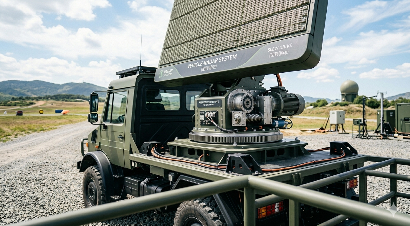
What Self-Locking Means in a Worm-Driven Slew Drive
In a worm gear set, the worm drives the wheel. Self-locking means the wheel cannot drive the worm when power is removed. It happens when the worm's lead angle is smaller than the friction angle of the mesh, so friction wins over the reverse torque.
As a rule of thumb, a self-locking worm set runs at lower efficiency than a non-locking one. That is the trade-off: you get holding without a separate brake, but you need more motor torque and you create more heat. A higher locking margin is not automatically better if it forces a larger motor or overheats the lubricant in a high duty cycle.
| Attribute | What it affects | Trade-off or limit |
|---|---|---|
| Lead angle | Sets the basic locking tendency of the mesh | Smaller angle holds better but lowers efficiency |
| Friction coefficient | Moves the real locking margin up or down | Changes with lubricant, temperature, surface finish, and run-in |
| Single vs. double worm | Changes torque capacity and load sharing | Locking must be verified on the actual configuration, not assumed from the type |
| Backlash | Affects how much the output moves before the mesh loads up | Backlash is not back-driving, but it can look like it in a sloppy test |
| Vibration environment | Can let the worm creep even when the static hold is good | Needs a separate test condition |
Spur gear drives work differently. They are generally not self-locking, so they depend on a brake motor or another holding device. If your design uses a spur unit, such as an SP-I Slew Drive, plan the holding method separately.
Static Holding vs. Back-Driving: The Misunderstanding That Changes Test Results
Many quick tests only push on the output by hand, see no motion, and call it self-locking. That proves the unit resists breakaway at one point, in one direction, at room temperature. It does not prove the load will stay put during a gust of wind, a stop from rated speed, or hours of machine vibration.
Static friction is normally higher than running friction. Once the mesh starts to slip, even slowly, the locking margin can fall. Vibration can trigger that slip, which is why a drive that holds on the bench may creep in the field.
Load direction matters too. Back-driving comes from tangential torque at the gear mesh, such as load times arm, wind torque, or inertia. Pure overturning moment and axial load do not turn the worm directly, but they change bearing friction and mesh contact. A test that applies only vertical weight may miss the torque path that actually matters.
| Question | Static holding check | Back-driving resistance check |
|---|---|---|
| What is applied? | Hand force or a single small torque | Rated tangential torque in both directions |
| Duration | Seconds | A hold period defined by your duty |
| Conditions | Cold, quiet, one position | Warm lubricant, vibration, multiple positions |
| What it proves | Breakaway resistance at one point | Whether the load creeps or reverses in service |
| Limit | Can pass a drive that fails in the field | Takes more setup, but matches real use |
Request Your Custom Slew Drive or Bearing Spec
Tell us your load, speed, and environment — receive a tailored 100–5000 mm slewing drive or slewing bearing proposal with 3D drawings within 24 hours.
A Practical Unloaded and Rated-Load Test Method That Separates Static Holding From Back-Driving Resistance
This method runs in two stages. The unloaded stage finds the baseline back-driving resistance of the drive itself. The rated-load stage shows what happens when your real torque tries to reverse it. In my design work, we write the pass limits into the drawing note before the test, never after.
Before you start
- Calculate the worst-case back-driving torque at the output ring: load times arm, wind torque, and inertia during a stop.
- Define the hold duration and allowable creep in your specification.
- Run the drive in until the lubricant reaches a normal working temperature, and record ambient and housing temperature.
- Mount a dial indicator or encoder at a known radius on the output so you can convert linear motion to angle.
- Disconnect any brake or holding device, or the test will prove nothing about the gear mesh.
Test steps
- Unloaded breakaway test. With the motor off and no payload, apply torque at the output with a calibrated torque wrench. Record the torque at which the output begins to turn the worm, in each direction. Repeat at positions about 90° apart, because mesh and bearing friction vary around the ring.
- Free-spin check. Try to turn the motor-side input by hand through the output load. If the output moves freely, the drive is not locking at all, regardless of the catalog.
- Rated-load hold. Apply your calculated tangential torque in one direction and hold it. Log the output position over time. Repeat in the opposite direction.
- Read the displacement curve. Backlash and elastic wind-up show as an initial step that then flattens. Back-driving shows as a continuing slope that does not stop.
- Dynamic stop test. Run the load at working speed, cut power, and measure coast distance. Check whether the load reverses after stopping.
- Vibration hold. Repeat step 3 while applying vibration similar to your machine, such as a running motor or shaker. Watch for slow creep.
- Repeat at temperature extremes. Test cold and hot, and again after a lubricant change if your service plan includes one.
Pass and fail readings
| Observation | Likely meaning | Action |
|---|---|---|
| Step in position, then flat line | Backlash take-up and elastic wind-up | Pass, if the step is within your allowed backlash |
| Continuous slope under rated torque | Real back-driving | Fail: add a brake or change the gear configuration |
| Holds static, creeps under vibration | Thin locking margin | Add a holding device or request a different ratio or lubricant |
| Passes cold, fails hot | Friction drops as the lubricant warms | Test at maximum service temperature and review the lubricant |
| Different results at each position | Uneven mesh or bearing friction | Check mounting flatness, and ask the supplier about mesh inspection |
Pass numbers must come from your own machine requirements. A tracker, a crane, and a steering system tolerate very different creep. If your acceptance limit is missing, define it first rather than copying a number from another project.
Common Mistakes When Verifying Self-Locking
- Testing with the brake still connected. The brake holds the load, and you learn nothing about the gears.
- Using weight only. Gravity may load the bearing but not produce tangential torque at the mesh.
- Testing at one position. Friction varies around the ring, so a single point can hide a weak spot.
- Ignoring temperature. A warm, thin lubricant lowers friction and can reduce locking.
- Confusing backlash with creep. Always plot position against time before calling a fail.
- Treating self-locking as a safety brake. For personnel lifting or critical loads, a mechanical or motor brake is the safer design, and self-locking is a supplement.
Where Holding Behavior Matters: Real Application Examples
Holding requirements show up in many industries. A South Korean port equipment manufacturer ordered 20 units of WEA9-62-25HR single worm slew drives for port crane systems, specified with tracking precision of 0.15° or better, IP65 sealing, and self-locking. A British Columbia forestry equipment maker ordered 30 units of WED14-86-25BHR.5 double worm drives for grapple machines with precision of 0.13° or better.
A Houston, Texas engineering machinery manufacturer ordered 150 units of WED17-104-25HR for heavy-duty wheel steering. These examples show where load holding and positioning are part of the specification. Your own test data, not another customer's result, should still decide whether a configuration fits your machine.
For these drive families, see our Worm Gear Slew Drive and Double Worm Slew Drive pages. If standard frames do not match your torque path or mounting, a Customized Slew Drive can be specified around your test results.

Buyer's Checklist Before You Release the Specification
Luoyang Slewring Bearing Co., Ltd. is ISO 9001:2015 certified. Every slewing bearing we build passes CMM three-coordinate inspection and dynamic load testing, and our Slew Drive Quality Control process is documented. We provide a technical proposal within 24 hours and a 48-hour technical response, with a 2-year extended quality warranty. Standard products start at 1 set and customized products at 5 sets, and sample orders are welcome, so you can run the test above on a real unit first.
Use this list before you finalize a drive:
- Have you calculated tangential back-driving torque at the output, including wind and stop inertia?
- Is your allowed creep and hold time written into the specification?
- Does the test cover both directions, several positions, and working temperature?
- Have you run a vibration hold, not only a static one?
- Does the design include a brake if the load is safety-critical?
- Have you asked the supplier for lead angle, ratio, lubricant type, and efficiency data for your exact model?
- Is a sample unit available so you can run the procedure before volume orders?
If any answer is missing, that gap is the next task. A drive that passes this sequence under your own load direction is far more likely to hold in the field than one chosen from a datasheet line.
Request Your Custom Slew Drive or Bearing Spec
Tell us your load, speed, and environment — receive a tailored 100–5000 mm slewing drive or slewing bearing proposal with 3D drawings within 24 hours.
 WhatsApp

 +8613903880726