



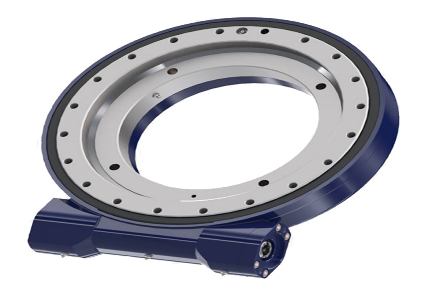
What is a slew drive? A slew drive is a compact rotary transmission assembly that combines a slewing bearing, gear system, housing, and mounting interfaces to rotate equipment such as cranes, solar trackers, work platforms, turntables, and material-handling systems.
The short answer to how to replace slew drive equipment is simple: do not approve the same model number until you confirm that the present machine still applies the same loads, mounting conditions, motion pattern, and environmental exposure. A replacement can fit the bolt pattern and still be wrong for the application.
This matters most for OEM maintenance teams and field service buyers. The original drive may have been selected for an earlier attachment, shorter boom, lighter payload, slower cycle, or cleaner operating environment. If any of those conditions changed, a direct replacement can create early gear wear, bearing damage, mounting-bolt issues, inaccurate positioning, or repeated downtime.
Luoyang Slewring Bearing Co., Ltd. supplies Slew Drive assemblies for industrial equipment and supports technical proposals within 24 hours. Our engineering review starts with the application load path, not only the part number stamped on the failed unit.
Start with the original drive data, then compare the current machine
A matching model number is useful, but it is only the first check. It confirms that the replacement may share dimensions, gear layout, and mounting interfaces with the original unit. It does not prove that the machine still operates within the original design conditions.
Begin by collecting records from the installed drive and the machine. If the original specification sheet is unavailable, measure the mounting interfaces and document the actual equipment configuration before selecting a replacement.
Information to collect before requesting a replacement quote
- Existing drive identification: model number, serial number, gear type, rotation direction, and motor or hydraulic drive arrangement.
- Mounting dimensions: housing diameter, center height, mounting-hole quantity, hole spacing, bolt size, gear position, and output connection details.
- Machine geometry: boom length, attachment length, payload location, offset from the rotation center, counterweight changes, and added accessories.
- Operating conditions: rotation speed, start-stop frequency, reversing frequency, daily operating hours, shock loading, wind exposure, vibration, and outdoor storage.
- Failure evidence: tooth damage, backlash increase, bearing looseness, oil or grease condition, bolt movement, housing cracks, and abnormal noise.
The best replacement decision compares the original machine condition with the current machine condition. If the equipment has the same attachment, load position, duty pattern, and environment, a same-model unit may remain appropriate. If the machine has been modified or now fails repeatedly, treat the replacement as a new selection task.
For example, a turntable that originally carried a centered fixture can develop a much higher overturning moment after a longer fixture arm is installed. The total payload may stay similar, but moving that payload farther from the rotation center changes the load applied to the drive.
| Check Item | What It Confirms | When a Same-Model Replacement May Work | When Further Engineering Review Is Needed |
|---|---|---|---|
| Model and mounting pattern | Physical fit and installation compatibility | Machine structure and interfaces are unchanged | New adapter plates, altered bolt pattern, or changed gear orientation |
| Payload and center of gravity | Axial and overturning loading | Same payload and same load position | Longer boom, heavier tool, offset attachment, or added counterweight |
| Rotation cycle | Gear and bearing fatigue demand | Similar speed, starts, stops, and daily operating pattern | More frequent reversing, automation upgrade, or continuous cycling |
| Environment | Sealing and corrosion exposure | Similar indoor or protected conditions | Salt spray, dust, washdown, desert exposure, or longer outdoor service |
| Failure history | Whether the prior selection was adequate | Failure was clearly caused by external damage or maintenance error | Repeated tooth wear, loose bolts, excessive play, or cracked mounting structure |
Do not use a physical fit as a load-capacity approval. Dimensions affect installation, while applied loads affect bearing life, gear contact, housing stress, and mounting-bolt demand. Both must be checked.
Know when a direct replacement fails after axial, radial, moment, or duty-cycle loads change
A direct replacement fails when the current application loads are no longer the loads used for the original selection. The four conditions that usually change the decision are axial load, radial load, overturning moment, and duty cycle. They interact, so reviewing one value alone can lead to a wrong conclusion.
| Parameter | What It Means at the Slew Drive | What It Affects in Practice | Common Change That Invalidates a Direct Replacement |
|---|---|---|---|
| Axial load | Load acting parallel to the rotation axis | Bearing raceway loading and support of vertical machine weight | Heavier platform, larger solar panel frame, added equipment, or increased lifted load |
| Radial load | Load acting sideways across the rotation axis | Raceway contact, gear alignment, and housing support behavior | Side pulling, conveyor interaction, side-mounted actuator force, or unstable travel conditions |
| Overturning moment | Rotational force created when a load acts away from the center | Bearing contact pattern, bolt loading, structural deflection, and positioning stability | Longer boom, extended grapple, offset payload, wind on a large panel, or longer work platform |
| Duty cycle | How often and how hard the drive operates over time | Gear wear, heat buildup, fatigue demand, lubrication condition, and backlash growth | Manual operation converted to automated cycling or more frequent start-stop movement |
Axial load alone does not tell the full story. A drive can support a vertical load in a static condition, yet experience a damaging combined condition when that load is offset from the rotation center. The offset creates overturning moment, and the bearing plus mounting structure must carry both effects at the same time.
Radial load can become more serious during movement. A side force that appears modest when equipment is stationary may rise during acceleration, deceleration, impact, or uneven terrain. This is common in mobile equipment, crane attachments, forestry tools, and machines that rotate while handling an off-center load.
Moment load often decides whether upsizing is required. Increasing arm length or moving a payload outward creates more leverage at the drive even when the payload weight does not change. A replacement selected only by total mass can therefore be undersized.
Duty cycle changes the fatigue picture. A drive used occasionally for manual positioning does not see the same operating demand as one that reverses repeatedly in an automated process. A same-size drive may physically fit, but it may not suit the revised cycle pattern.
The practical boundary is clear: use a direct replacement only when the load directions, load positions, motion sequence, cycle frequency, and environment remain materially unchanged. If one of these inputs has changed, request a fresh load review and consider a larger standard unit or a Customized Slew Drive.
Review the full load path instead of checking the drive in isolation
A slew drive does not operate alone. The load passes through the attachment, machine frame, mounting bolts, drive housing, internal bearing, gear teeth, and motor or hydraulic system. A problem in any part of that path can make a correctly selected replacement appear to fail.
Start at the applied load and trace it back to the machine structure. Look for new brackets, welded reinforcements, spacer plates, bent supports, loose fasteners, or worn mating surfaces. These conditions can shift load distribution and increase stress on the drive.
Four questions that expose load-path problems
- Has the load moved farther from the rotation center? If yes, calculate or provide the new load offset. A longer reach generally increases overturning demand.
- Has the attachment become heavier or less balanced? Check added tools, guards, hoses, cameras, clamps, platforms, and replacement components.
- Has the machine frame changed? Added plates can improve support, but poorly aligned adapters can introduce distortion or uneven bolt loading.
- Has operation become more dynamic? Identify sudden stops, reverse rotation, impact loading, travel over rough surfaces, wind effects, and automated cycle changes.
Mounting bolts deserve close attention. A drive housing can be correctly sized while the bolt joint is not. If bolts loosen repeatedly, the root cause may be insufficient preload, damaged threads, an uneven mounting face, structural flexing, or a load condition beyond the original design basis.
Check the mounting faces for flatness, contamination, corrosion, paint buildup, and damage. A distorted interface can prevent even support around the drive and concentrate load in a limited area. Replacing only the drive without correcting the mating structure may repeat the failure.
Gear system selection also matters. A Worm Gear Slew Drive is commonly selected where controlled rotation and self-locking characteristics are required, but the final choice still depends on the machine load case and motion requirements. Where higher stability under demanding loading is needed, a Double Worm Slew Drive may be evaluated, subject to engineering confirmation.
Request Your Custom Slew Drive or Bearing Spec
Tell us your load, speed, and environment — receive a tailored 100–5000 mm slewing drive or slewing bearing proposal with 3D drawings within 24 hours.
Use failure symptoms to decide whether the old size is still suitable
A failed drive does not automatically mean that the model was undersized. It may have been damaged by poor lubrication, contamination, incorrect installation, external impact, or a loose mounting joint. Still, repeated symptoms should trigger a load and application review before ordering another identical unit.
| Observed Symptom | Possible Load-Related Meaning | Immediate Verification Step | When the Same Model Should Not Be Approved Yet |
|---|---|---|---|
| Repeated increase in rotational play | Wear may be accelerated by moment load, shock, or high cycle demand | Inspect attachment offset, work cycle, raceway condition, and mounting bolts | The same symptom occurred on multiple replacement units |
| Gear tooth wear or abnormal noise | Possible high torque demand, poor engagement, contamination, or misalignment | Check drive alignment, motor setup, lubrication condition, and operating resistance | Teeth show repeated damage after correct installation and maintenance |
| Loose mounting bolts | Possible joint movement, structural flexing, or changed moment loading | Inspect bolt condition, mounting-face condition, and frame stiffness | Bolts loosen again after the specified assembly procedure |
| Cracked bracket or adapter plate | Load path may be concentrating stress outside the original design | Inspect welds, plate thickness, support location, and attachment geometry | Any crack is present near the drive mounting area |
| Positioning drift during rotation | May involve backlash, load shift, gear wear, or changing external force | Record the direction, load condition, and timing of the drift | Accuracy is required for lifting, tracking, or automated positioning |
Do not diagnose from one symptom alone. Gear noise may be a lubrication issue, while repeated gear damage under the same duty pattern may point to overload or misalignment. The decision should use inspection evidence, the actual load case, and the machine’s operating history.
Luoyang Slewring Bearing Co., Ltd. uses CMM three-coordinate inspection and dynamic load testing as part of its stated quality process for slew bearings. For replacement projects, dimensional control is necessary, but it does not replace application verification. A correctly manufactured unit still needs correct selection and installation.
Follow a practical approval procedure before issuing a purchase order
Use a short engineering gate before buying a replacement. This protects maintenance schedules without treating speed as a reason to skip technical checks. It also gives purchasing teams a clear record of why a same-model replacement was accepted, rejected, or changed.
- Identify the installed unit. Photograph the nameplate, mounting faces, gear orientation, motor connection, and visible damage. Record the old model number but do not treat it as final approval.
- Document current machine configuration. List the present attachment, payload, load center, operating angle, added accessories, and environmental conditions.
- Compare current conditions with original conditions. Ask whether payload, reach, attachment geometry, rotation frequency, operating speed, or environment changed after initial commissioning.
- Inspect the complete mounting system. Check bolts, threads, adapter plates, structural welds, mounting-face condition, and any signs of movement.
- Classify the outcome. Approve a same-model replacement only when the application is unchanged and the failure cause is understood. Request engineering review when loads, duty cycle, structure, or failure pattern changed.
- Submit a technical package. Provide drawings, photographs, load information, duty description, mounting dimensions, and the desired replacement timeline.
This process is especially useful when downtime creates pressure to order immediately. A same-model unit can be the fastest route when the application has not changed. It is not the right shortcut when the replacement will face higher loading than the unit it replaces.
Our standard product MOQ is one set, which supports maintenance replacements and evaluation orders. For a changed application, customized products have a five-set MOQ, and samples are welcome for testing and evaluation when appropriate to the project.
Match the replacement path to the machine and service environment
There are three practical replacement paths: direct same-model replacement, standard upsizing, or a custom design review. The right path depends on whether the interface, load case, and operating conditions remain stable.
| Replacement Path | Best-Fit Situation | Main Benefit | Limit |
|---|---|---|---|
| Same-model replacement | Unchanged machine, unchanged load case, and known non-load-related failure cause | Fastest path with minimal interface changes | Not suitable when reach, payload, duty cycle, or mounting structure changed |
| Standard upsized slew drive | Higher load demand exists, but a suitable standard mounting solution can be adopted | May improve load margin without a fully new design | Can require new brackets, motor changes, or revised mounting interfaces |
| Custom slew drive | Machine has special geometry, unusual load direction, special environment, or nonstandard interface | Allows the drive, gearing, mounting, and protection needs to be reviewed together | Requires complete application data and engineering approval |
Environmental conditions can alter the replacement decision even when mechanical loads remain similar. Outdoor solar equipment, marine cranes, mining machines, and dusty industrial systems may need a sealing and corrosion approach suited to the actual service site. Luoyang Slewring Bearing Co., Ltd. offers slew drive protection up to IP66 and anti-corrosion rating up to C4H, selected according to the working environment rather than applied as a default to every unit.
Real application context matters. A South Korean port equipment manufacturer placed a repeat order for 20 WEA9-62-25HR single worm slew drives for port crane systems, with stated tracking precision of no more than 0.15 degrees, IP65 sealing, and self-locking performance. That case supports the need to match a drive to a defined crane application; it does not mean the same model is suitable for every port crane or every modified machine.
For heavy cyclic applications, review the actual motion and load direction before selecting a replacement. An Australian heavy equipment manufacturer used HWE21-94-25HR.1 double worm slew drives for mining excavators, while a British Columbia forestry equipment manufacturer used WED14-86-25BHR.5 double worm slew drives for forestry grapple machines with stated precision of no more than 0.13 degrees. These are application-specific examples, not universal sizing rules.
When the original drive data is incomplete, send the available nameplate photographs, installation drawings, failure photographs, and current machine details for review. Our ISO 9001:2015-certified facility has six production lines and an annual capacity of 100,000 sets, while our engineering team can prepare a technical proposal within 24 hours based on adequate application information.
A replacement decision is sound when the part fits, the load path is verified, the duty cycle is understood, and the mounting structure is confirmed. If the machine has changed, the safest replacement is not necessarily the same model. It is the model that matches the current equipment condition.
Request Your Custom Slew Drive or Bearing Spec
Tell us your load, speed, and environment — receive a tailored 100–5000 mm slewing drive or slewing bearing proposal with 3D drawings within 24 hours.
 WhatsApp

 +8613903880726