



What is a slew drive? A slew drive is a compact rotary transmission unit that combines a slewing bearing, gear set, housing, and drive input to rotate equipment such as solar trackers, cranes, turntables, and lifting platforms.
The main question in how to replace slew drive assemblies is not simply how to remove the old unit. The real challenge is installing the replacement without shifting the mounting relationship, changing gear engagement, or creating side load at the input connection. A planned changeout should leave the equipment rotating in the same intended path as before removal.
This guide is for maintenance engineers and equipment technicians preparing a scheduled replacement before ordering parts or taking the machine out of service. It covers the checks that must happen before downtime, the physical replacement sequence, alignment controls, and post-installation verification.
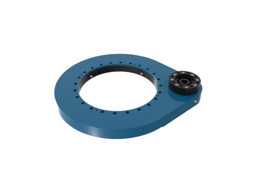
Confirm the Replacement Scope Before Scheduling Downtime
Start by proving that the slew drive is the failed component and that the replacement unit matches the installed interface. Replacing a drive without checking the connected structure can leave the same operating problem in place, especially when the mounting frame is distorted or the driven equipment has excessive resistance.
Record the identification information from the installed unit before removing guards or disconnecting the motor. The model designation, gear arrangement, mounting-hole pattern, output position, input orientation, rotation direction, and electrical or hydraulic drive details all affect replacement compatibility.
Collect the information that blocks a correct replacement
- Drive model and serial information: Photograph the nameplate and record all visible markings. This prevents ordering a similar-looking unit with a different center distance or mounting arrangement.
- Installed orientation: Record which side faces the operator, boom, panel row, turntable, or machine frame. Mark the top, output side, motor side, and direction of normal rotation.
- Mounting interface: Measure the mounting-hole locations, bolt size, plate thickness, and clearance around the housing. Compare these details to the supplier drawing before purchase.
- Driven load condition: Identify whether the load is held by a brake, cylinder, counterweight, mechanical stop, or external support. The slew drive must not be treated as the only support during removal.
- Input connection: Check whether the drive uses a hydraulic motor, electric motor, gearbox, coupler, sprocket, or shaft connection. A replacement may fit the base mounting but still require a different adapter or coupling position.
Do not order only by outside dimensions. Similar housings may use different worm positions, gear ratios, output interfaces, or load directions. This is especially relevant when replacing a Worm Gear Slew Drive, where the worm position and motor mounting side determine how the equipment rotates.
Inspect the old drive and surrounding machine before confirming the order. Look for cracked mounting plates, elongated holes, fretting marks, bent adapters, damaged bolt threads, oil leakage, and misaligned shafts. If the base plate has moved or the equipment structure is bent, installing a new unit will not correct the root cause.
| Pre-replacement check | What to record | Why it matters | When it does not solve the issue |
|---|---|---|---|
| Drive identification | Model, ratio, input and output arrangement | Confirms functional compatibility | It does not confirm whether the machine frame is flat |
| Mounting pattern | Hole locations, bolt sizes, plate condition | Prevents forced fitment or hole modification | It does not verify gear mesh with external gears |
| Rotation direction | Normal forward and reverse movement | Prevents reversed motor or control connections | It does not prove final travel limits are correct |
| Connected load | Weight support and restraint method | Controls movement during removal | It does not replace a formal lifting plan |
Luoyang Slewring Bearing Co., Ltd. can provide a technical proposal within 24 hours when the application information is complete. Standard products are available from one set, while customized products start from five sets. That support is useful when an installed unit has a nonstandard motor position, mounting interface, or environmental requirement.
Prepare the Machine, Tools, and Reference Marks Before Removal
A successful replacement starts with reference marks made while the old drive is still in its known operating position. These marks let the installation team restore the same relationship between the slew drive, base frame, driven structure, and external gear or coupling.
Park the machine on stable ground and move the rotating structure to a position with safe access to bolts, lifting points, and drive connections. Avoid stopping at a mechanical end stop unless the equipment manufacturer specifically requires that position. A stop can hide preload, side load, or contact that makes removal harder.
Prepare these items before lockout
- Approved lifting equipment sized for the replacement unit and attached components.
- Blocking or external supports for the boom, platform, tracker row, turntable, or other rotating load.
- Paint marker, center punch, straightedge, calipers, feeler gauges, and a camera.
- Cleaning materials for mounting faces, bolt holes, adapters, and couplings.
- Replacement mounting hardware if the equipment manufacturer requires new bolts or if existing fasteners are damaged.
- The machine manufacturer’s bolt torque, tightening sequence, lubricant, and acceptance instructions.
Lock out electrical, hydraulic, pneumatic, and stored mechanical energy before disconnecting the drive. Verify that the rotating structure cannot move when the motor is disconnected. A hydraulic motor can retain pressure, and a vertical or offset load can rotate when the drive is released.
Mark the position of the housing against the fixed mounting plate. Add a second mark between the drive output connection and the driven member. If an external pinion, ring gear, or coupling is involved, mark a tooth reference or coupling index point so the original engagement can be restored.
Take photographs from directly above and from each side. Include a ruler or known reference dimension in at least one photo. This gives the team a record of cable routing, hose orientation, motor position, shim location, and clearance to nearby machine parts.
Request Your Custom Slew Drive or Bearing Spec
Tell us your load, speed, and environment — receive a tailored 100–5000 mm slewing drive or slewing bearing proposal with 3D drawings within 24 hours.
Preserve Mounting-Face Alignment and Gear Mesh During Removal and Installation
The correct method is to preserve physical references before the old unit moves, then install the new drive against clean and verified mounting surfaces. Do not use mounting bolts to pull a drive into position against dirt, burrs, warped plates, or incorrect shims. That practice can twist the housing and alter gear engagement.
Use the following sequence when the replacement drive connects directly to a turntable, external gear, pinion, coupling, or driven arm. The exact torque values and final backlash criteria must come from the equipment and drive manufacturer. They depend on the machine design and are not interchangeable between applications.
- Support the driven structure. Install approved stands, restraints, or lifting support before loosening the slew drive. Confirm that the load remains stable with the drive disconnected.
- Index the existing position. Draw witness lines across the drive housing and fixed base plate. Mark the driven member to the output flange, gear, or coupling. Photograph each mark before removal.
- Measure any shim pack. If shims are present, record their location, count, and thickness arrangement. Keep each shim group labeled by position. Do not mix shims from opposite sides.
- Release the input connection. Disconnect the motor, coupling, hoses, wiring, or brake connection according to the machine procedure. Cap hydraulic lines and protect electrical connectors from contamination.
- Loosen bolts in a controlled pattern. Release mounting bolts gradually and in an alternating pattern. Watch for housing movement, trapped load, or a plate that springs after bolt tension is removed.
- Lift straight and clear. Attach lifting equipment to approved lifting points. Lift vertically enough to clear locating surfaces, then move the unit away without dragging it across the mounting face.
- Clean and inspect both faces. Remove rust scale, old sealant, paint buildup, burrs, and loose debris. Check for raised metal around bolt holes and fretting marks that indicate movement.
- Dry-fit the new unit. Set the replacement in place without forcing bolts. Confirm that it sits flat, the marked orientation matches, and the input connection reaches without side pull.
- Restore shims only when required. Reinstall the documented shim arrangement if it is part of the original machine setup and the mounting faces are unchanged. Do not add random shims to correct an unexplained gap.
- Align to reference marks. Bring the new housing witness marks into the original position. Align the output mark, gear tooth reference, or coupling index before tightening fasteners.
- Install and tighten mounting bolts. Follow the equipment manufacturer’s specified bolt grade, lubrication condition, sequence, and torque. Tighten in stages using an alternating pattern so the housing seats evenly.
- Reconnect the input without forcing it. The motor, coupling, or adapter should mate naturally. If bolts are needed to draw parts together, stop and check shaft alignment, adapter length, and orientation.
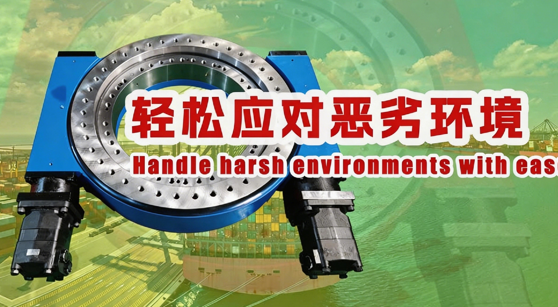
Use these checks to protect gear mesh
| Check point | Acceptable observation | Likely failure reason if incorrect | Recovery action |
|---|---|---|---|
| Mounting-face contact | Housing sits flat without bolt force | Debris, burrs, warped plate, wrong shim stack | Remove the unit and correct the contact surface |
| Witness-mark position | New housing aligns with recorded references | Incorrect orientation or shifted base position | Loosen before final torque and reset position |
| External gear engagement | Rotation feels consistent through the working arc | Center distance changed or gear position shifted | Recheck mount location, shims, and gear reference |
| Coupling fit | Coupling engages without side force | Motor adapter or drive input is misaligned | Correct adapter position before operating |
Do not judge mesh at only one rotational position. A bent frame, distorted ring, or uneven mounting face may produce acceptable engagement in one area and binding in another. Rotate the equipment through the available safe travel range during the inspection stage.
Where load capacity or interface dimensions differ from a standard catalog unit, a Customized Slew Drive may be more appropriate than modifying the machine frame. Luoyang Slewring Bearing Co., Ltd. selects ductile cast iron, alloy steel, stainless steel, or forged alloy steel according to load, speed, and environmental conditions.
Inspect the New Installation Before Returning Equipment to Service
Final verification should begin before full-power operation. The goal is to identify binding, misalignment, leakage, loose hardware, wrong rotation, or control interference while the equipment can still be stopped safely.
First, inspect the drive at rest. Confirm that all mounting bolts are installed, the input connection is secured, hoses and cables have clearance through the full intended movement, and guards can be refitted without touching the housing or motor.
Perform a controlled functional check
- Remove tools, lifting equipment, temporary restraints that are no longer needed, and loose hardware from the rotation area.
- Energize the input system according to the machine’s startup procedure.
- Jog the drive in the normal direction at the lowest available controlled speed.
- Stop and inspect for unexpected housing movement, abnormal noise, visible gear interference, hydraulic leakage, or cable tension.
- Jog in the reverse direction if the machine is designed for reverse operation.
- Run through the safe operating range while observing the gear engagement, hose movement, and support structure.
- After the test, recheck mounting fasteners and inspect the witness marks for any shift.
A smooth movement pattern is the expected result. A repeating tight spot, knock, or sudden motor-load change points to a problem that must be investigated before normal production service. Do not continue operating to “wear in” a binding gear mesh; this can damage the new drive, external gear, or mounting structure.
For solar tracking systems, verify tracker travel and cable routing after replacement because a reversed orientation can send the row in the wrong direction. For crane, platform, and turntable equipment, verify that motion stops and limit devices function as intended before lifting or carrying a working load.
Luoyang Slewring Bearing Co., Ltd. supplies Slew Drive products with protection ratings up to IP66 and anti-corrosion performance up to C4H for specified applications. The correct protection level still depends on the actual exposure, sealing arrangement, maintenance practice, and installation quality.
Recognize Replacement Errors Early and Choose the Right Recovery Path
The fastest recovery is usually to stop at the first abnormal sign and return to the last confirmed alignment point. Continuing a test after binding or housing movement can turn a mounting issue into a damaged gear set or distorted interface.
- Error: The replacement drive will not sit flat. Do not tighten bolts to close the gap. Remove the unit, clean the faces, inspect for raised metal, and compare the new interface to the old unit.
- Error: The motor or coupling will not line up. Do not pull the connection together with bolts. Recheck the input orientation, adapter thickness, shaft position, and original witness marks.
- Error: Rotation is reversed. Stop immediately and review motor wiring, hydraulic hose connections, and the documented rotation direction. This is common when the drive orientation has been mirrored during installation.
- Error: Gear engagement tightens at one point. Inspect the base plate, external gear runout, shim arrangement, and mounting-face cleanliness. The cause may be outside the slew drive itself.
- Error: Housing marks shift after testing. Check bolt specification, tightening sequence, mounting plate integrity, and load restraint. Fretting or movement means the joint is not holding position.
Replacement planning also affects purchasing risk. For example, an Australian heavy-equipment manufacturer selected HWE21-94-25HR.1 double worm slew drives for mining excavators, while a Canadian forestry equipment manufacturer used WED14-86-25BHR.5 double worm slew drives for forestry grapple machines with stated tracking precision of no more than 0.13 degrees. These examples show why load direction, holding needs, application movement, and operating environment must be reviewed before selecting a replacement design.
For heavy cyclic loads or applications with a separate bearing and transmission arrangement, inspect the related Slewing Bearing as part of the same maintenance event. A worn bearing, damaged mounting ring, or loose structural connection can create symptoms that appear to be a drive failure.
Luoyang Slewring Bearing Co., Ltd. operates an ISO 9001:2015 quality management system and offers a two-year extended quality warranty, with free replacement for confirmed manufacturing defects. For projects that need design confirmation before downtime, provide equipment photos, old-drive identification, mounting dimensions, load details, and operating conditions so the replacement proposal can address the actual interface rather than only the product size.
Request Your Custom Slew Drive or Bearing Spec
Tell us your load, speed, and environment — receive a tailored 100–5000 mm slewing drive or slewing bearing proposal with 3D drawings within 24 hours.
 WhatsApp

 +8613903880726