



What is a custom slew drive? It is a slewing bearing, gear set and housing built as one rotation unit and engineered around your load case, not a catalog rating. A custom slew drive for special vehicle platforms has to survive tilting moments, road shock and repeated duty cycles. If those inputs never reach the supplier, you may find the undersizing only after the prototype fails.
This guide shows how to turn vehicle loads into a specification a supplier can validate. It also covers what evidence to request and which cooperation terms to settle before you release the platform design. I write it from three decades of mechanical design work on cranes, port equipment and heavy machinery, so the focus is on what actually goes wrong in RFQs.
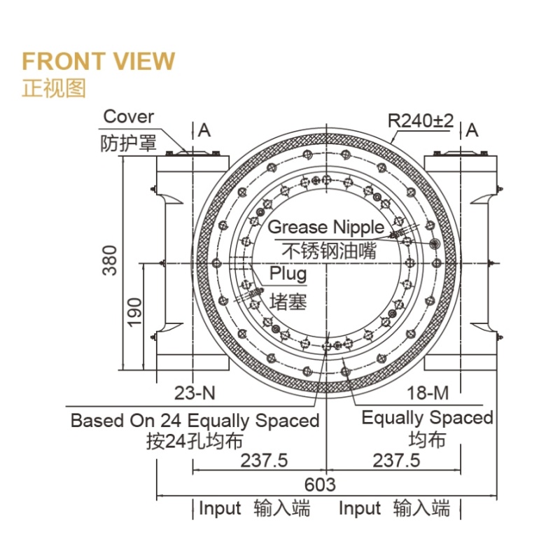
Why Catalog Ratings Alone Fall Short on Special Vehicles
A catalog rating describes a drive under defined test conditions. A vehicle rarely matches those conditions. It brakes, climbs slopes, drops onto outriggers and swings loads at awkward angles.
Many supplier pages promise "custom solutions" or "ready-to-mount assemblies." Few explain how your load inputs become a validated design. That gap is where the sourcing risk sits.
Common mistakes in vehicle slew drive RFQs
- Sending only a static payload. A static weight hides the overturning moment, which usually drives bearing size.
- Ignoring shock events. A sudden stop or wheel strike can exceed the steady load by a wide margin.
- Leaving out duty cycle. Ten swings a day and ten swings a minute need different gear and wear designs.
- Skipping the mounting structure. A flexible chassis ring distorts the bearing and shortens its life.
- Treating environment as an afterthought. Salt, dust and wash-down change the sealing and coating needs.
Turn Vehicle Loads Into a Supplier-Ready Specification
This step prevents undersizing. A supplier cannot size a drive from a payload figure alone. Give it five load inputs plus the environment, and write each one as a number with a condition attached.
| Input | What to give the supplier | Undersizing risk if omitted |
|---|---|---|
| Overturning moment | Maximum moment at the worst boom, arm or payload position, with load distance | Raceway edge loading, bolt overload, bearing tilt |
| Radial load | Horizontal forces from braking, slopes, wind and swing acceleration | Gear tooth and bearing radial overload |
| Axial load | Upper structure dead weight plus payload, including lifting dynamics | Early raceway fatigue |
| Shock events | Type, peak value and frequency, such as emergency stops or outrigger drops | Tooth breakage, raceway denting |
| Duty cycle | Rotation angle, speed, rotations per hour, dwell time under load | Wear, overheating, wrong gear type |
| Environment | Dust, water, salt, temperature range, wash-down | Seal failure, corrosion |
Four steps to build the load case
- Find the worst position. Locate the pose that gives the highest moment, not the most common pose.
- Separate steady and peak loads. List normal operation, then each shock event with its estimated frequency.
- Add holding needs. State whether the drive must hold position on a slope or when parked. This points toward self-locking designs.
- Document the interface. Share the mounting flange stiffness, bolt pattern and available envelope.
The limit: if you do not yet know the shock loads, say so. A good supplier will ask for the vehicle type and operating profile and propose a conservative assumption. Flag it as an assumption in the drawing, and confirm it with testing on your prototype.
A worked scenario
Take a truck-mounted loader crane. The steady load is the boom and payload. The real design driver is the moment at full reach, plus the jolt when the operator brakes the swing with a load out. If the RFQ lists only "payload," the supplier may size around axial load and miss the moment. Listing the reach, swing speed and braking behavior lets the engineer check the bearing and gear mesh together.
Match the Drive Type to the Load Case
Drive type depends on torque, precision, holding and shock. No single type fits every special vehicle. The table gives a starting point, not a final choice.
| Drive type | Best fit | Limit to watch |
|---|---|---|
| Worm Gear Slew Drive | Compact crane and deck systems needing self-locking and smooth rotation | Lower efficiency, so check heat on continuous duty |
| Double Worm Slew Drive | Higher torque, shared load across two worms, such as steering or grapple systems | Larger envelope and more mounting space |
| Spur Gear Slew Drive | Higher efficiency and speed, such as turntable and tracker use | Does not self-lock without a brake |
Existing platforms offer useful reference points. Our Truck Crane Slewing Drive, Pump Truck Slewing Drive and Aerial Work Vehicle Slew Drive pages show the types of vehicle we already support. When none fits, a Customized Slew Drive starts from your drawings.
Request Your Custom Slew Drive or Bearing Spec
Tell us your load, speed, and environment — receive a tailored 100–5000 mm slewing drive or slewing bearing proposal with 3D drawings within 24 hours.
Evidence to Ask For Before You Trust a Supplier
Claims are easy and evidence is harder. Ask which load cases the supplier has already engineered around, and what they can document. Here is what Luoyang Slewring Bearing Co., Ltd. can point to.
| Buyer concern | Supporting fact or case |
|---|---|
| Shock and heavy duty | A Houston, Texas engineering machinery manufacturer ordered 150 units of WED17-104-25HR double worm slew drives for heavy-duty wheel steering systems. |
| Vehicle-mounted cranes | A Netherlands material handling equipment manufacturer ordered 50 units of WEA9-62-25HR for truck-mounted loader cranes. |
| Tight positioning | A British Columbia forestry equipment manufacturer ordered 30 units of WED14-86-25BHR.5 for grapple machines, at a precision of 0.13° or better. |
| Repeat orders and sealing | A South Korean port equipment manufacturer placed a 20-unit repeat order of WEA9-62-25HR drives (0.15° or better tracking precision, IP65 sealed, self-locking). |
| Rotation platforms | A Houston, Texas manufacturer ordered 100 units of SEA21-125-25HR(2) for slewing platform systems. |
These cases show the drive families in use. They do not guarantee that your load case matches theirs, and your own validation still applies.
Quality and process facts
- ISO 9001:2015 certified quality management system, with CE marking for the European market and factory audit reports available on request.
- CMM three-coordinate inspection and dynamic load testing on every slewing bearing. Read more on our Slew Drive Quality Control page.
- Protection up to IP66 and anti-corrosion ratings up to C4H for harsh industrial environments.
- Materials chosen per working condition: ductile cast iron, alloy steel, stainless steel or forged alloy steel.
- Engineering and machining from an experienced engineering team, CNC machining centers and 6 production lines in an 8,000 m² facility, established in 2012.
Ask any supplier, including us, for the inspection report format and the audit document before you commit. If a certificate is claimed, ask to see its scope.
Cooperation Terms and Boundaries
Clear terms prevent disputes after the first prototype. These are the conditions we can state today.
- MOQ: 1 set for standard products, 5 sets for customized products. Sample orders are welcome for testing and evaluation.
- Technical proposal: within 24 hours of receiving your requirements.
- Lead time: 3-day rapid prototyping and a 9-day standard production cycle. Complex custom designs and special materials may need more time, so confirm the schedule against your drawing.
- Capacity: 100,000 sets per year.
- Support and warranty: 48-hour technical response, a 2-year extended quality warranty and free replacement for confirmed manufacturing defects.
Some points still need written agreement for each project. These include acceptance criteria, who owns the load assumptions, test witness requirements and what counts as misuse. The warranty covers manufacturing defects, so a drive run beyond the stated load case is a separate matter. Settle that before the first order.
Buyer's Checklist Before You Send the RFQ
A complete request shortens the cycle and cuts the chance of resizing later. Collect these items for the supplier:
- Vehicle type and operating profile, with worst-case pose.
- Overturning moment, radial load and axial load, each with its condition.
- Shock events with peak value and expected frequency.
- Rotation angle, speed, rotations per hour and holding requirement.
- Precision target, such as a tracking tolerance in degrees.
- Environment, including the sealing level and corrosion class you expect.
- Mounting interface drawings and available space.
- Quantity for the prototype and expected annual volume.
If you are comparing suppliers for a custom slew drive for special vehicle programs, send these items to Luoyang Slewring Bearing Co., Ltd. and we will review them against our Slew Drive and Slewing Bearing ranges. Missing inputs are fine. We will tell you which assumptions to confirm and quote on what is known.
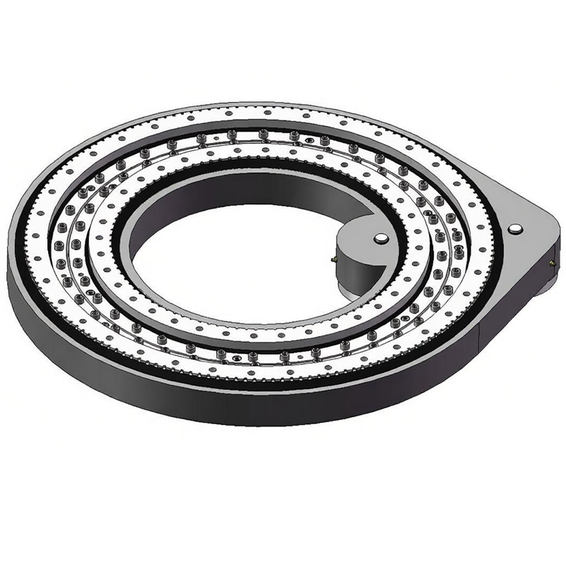
Request Your Custom Slew Drive or Bearing Spec
Tell us your load, speed, and environment — receive a tailored 100–5000 mm slewing drive or slewing bearing proposal with 3D drawings within 24 hours.
 WhatsApp

 +8613903880726