



What is a truck crane slewing bearing? It is the large rotational bearing installed between the crane upper structure and the carrier or chassis interface. It allows the boom, counterweight, cab, and hoisting system to rotate while supporting vertical force, side force, and tipping force at the same time.
A Truck Crane Slewing Bearing does not carry one simple load. During lifting, it usually receives axial load from the crane upper, radial load from side forces, and overturning moment from the boom radius and suspended load. The bearing raceways, rolling elements, mounting bolts, and supporting structures must work together as one load path.
For crane engineers and maintenance managers, the key question is not only whether the bearing has enough rated capacity. The more useful question is whether the full mounting system can transfer combined loads without raceway damage, bolt loosening, structural distortion, or excessive rotation clearance.

Combined crane loads must be evaluated as one system
The direct answer is simple: the bearing transfers forces through its rolling elements and raceways, while the bolts clamp the inner and outer rings to the crane structures. However, the real behavior becomes more demanding because the loads act together and change as the boom swings, lifts, lowers, and changes radius.
Axial force pushes the rings together or pulls them apart. Radial force tries to shift one ring sideways relative to the other. Overturning moment attempts to tilt the upper structure around the bearing centerline, concentrating load on one section of the raceway and reducing contact on the opposite section.
The bearing should therefore be selected as part of the full crane interface. A high-capacity ring cannot compensate for a thin mounting plate, weak bolt circle, uneven support surface, or loose bolts. Likewise, an oversized bolt may not solve a problem caused by insufficient ring stiffness or local chassis deflection.
| Load type | Typical truck crane source | Primary load path | What changes in practice |
|---|---|---|---|
| Axial load | Upper structure weight, boom weight, suspended load | Upper ring, rolling elements, lower ring, supporting frame | Increases rolling contact stress and compressive force at the mounting faces |
| Radial load | Wind, boom side loading, travel vibration, off-center motion | Raceway shoulders and rolling elements | Can increase side clearance, wear, and uneven rolling-element loading |
| Overturning moment | Boom radius, lifted load, counterweight, upper structure offset | Loaded raceway zone, opposite bolt groups, ring sections | Creates the highest local load concentration and bolt tension demand |
| Dynamic load | Starting, stopping, slewing, load swing, shock | Entire bearing and mounting system | Can raise peak forces beyond the static lifting condition |
The practical conclusion is that combined-load selection should use the actual working envelope, not only the maximum lifted weight. A short boom at a small radius may produce one load pattern, while a long boom at a large radius can create much higher overturning moment even with a lower lifted load.
This approach fits new crane design, bearing replacement, and duty-cycle review. It does not replace the crane manufacturer’s structural calculations, because boom geometry, outrigger condition, upper-frame rigidity, and allowable duty class can change the result.
How axial, radial, and overturning-moment loads transfer through the raceways and mounting bolts
The raceways carry the rolling contact forces. The mounting bolts hold the bearing rings against their support structures and prevent ring separation or relative movement at the interfaces. These two functions are connected, but they are not interchangeable.
When the crane upper rotates under mostly vertical load, axial force passes from the upper mounting structure into one bearing ring. The rolling elements transmit that force across the raceway contact zones to the opposite ring, and then into the lower supporting structure. The load is shared by multiple rolling elements, but it is not always shared equally around the full circumference.
Under radial load, the upper and lower rings attempt to move sideways relative to each other. The rolling elements and raceway geometry resist that displacement. Excessive radial clearance, worn raceways, or distorted mounting faces can reduce the intended contact pattern and increase localized stress.
Overturning moment is often the governing condition for a truck crane. When the boom acts at a radius, one side of the bearing is heavily compressed while the opposite side tends to separate. The compressed side carries higher rolling-element contact force. On the separating side, bolt preload and bolt tensile capacity become more significant.
| Component | Its role in combined loading | What to verify | What it cannot correct |
|---|---|---|---|
| Raceways | Provide the rolling contact path between bearing rings | Contact condition, wear pattern, lubrication condition, clearance trend | Cannot offset a weak or distorted mounting structure |
| Rolling elements | Transfer load between the rings while allowing rotation | Load zone behavior, smooth rotation, abnormal noise or vibration | Cannot evenly redistribute load if the rings are tilted by poor support |
| Inner and outer rings | Spread load around the bearing circumference and transmit it to the mounting faces | Flat support, full contact, ring condition, gear alignment where applicable | Cannot maintain design stiffness if the crane frame bends locally |
| Mounting bolts | Clamp the rings to the crane upper and chassis interface | Specified tightening method, preload retention, bolt condition, hole integrity | Cannot substitute for correct bearing capacity or proper support flatness |
| Mounting plates and frames | Provide the support stiffness behind the bearing rings | Flatness, weld condition, local bending, corrosion, deformation | Cannot be ignored because the bearing itself has a high load rating |
A common misunderstanding is that the bearing alone carries the tipping force. In reality, overturning moment is resisted by a system: compression through the loaded raceway zone and tensile restraint through the clamped ring and bolt circle on the unloading side.
Another misunderstanding is that every bolt receives the same force. Under moment load, bolt demand changes around the circle. Bolts near the separating side may experience higher tensile demand, while bolts nearer the compressed side mainly maintain clamp force and interface stability.
For this reason, bolt torque should never be treated as a casual maintenance item. Use the crane or bearing supplier’s documented bolt specification, tightening sequence, and inspection method. A generic torque value is not suitable because bolt size, grade, lubrication, thread condition, and joint design affect the result.
Mounting stiffness and bolt-circle condition can change bearing life
The bearing needs a flat, sufficiently rigid support surface. If the crane upper frame or chassis mounting face bends under load, the bearing rings can deform with it. That deformation reduces the intended load-sharing pattern and may concentrate rolling contact in a smaller raceway sector.
A stiff support structure is especially relevant when the boom is at long radius or when the crane repeatedly handles loads in one working direction. In those conditions, the same bearing sector and bolt groups can see repeated high loading. This does not mean every crane needs a thicker support plate; it means the support structure must be evaluated with the actual duty cycle and mounting geometry.
The bolt circle also affects load transfer. A larger effective bolt circle can provide better resistance to ring separation for a given moment, but bolt circle diameter alone is not a selection rule. Bolt quantity, bolt arrangement, ring design, joint stiffness, preload, and support structure behavior must be evaluated together.
When replacing an existing bearing, reuse of the old bolt pattern requires care. Matching the outside diameter and mounting holes is not enough. The replacement must also suit the crane’s axial load, radial load, overturning moment, gear arrangement, rotation requirements, and interface dimensions.
Luoyang Slewring Bearing Co., Ltd. supports bearing projects with an experienced engineering team, CNC machining centers, and CMM three-coordinate inspection. Our ISO 9001:2015-certified facility can provide technical proposals within 24 hours when the available crane data is sufficient for review.
For applications that need a related transmission assembly rather than a free-rotating ring alone, a Slew Drive may combine a slewing ring with an enclosed drive arrangement. This option suits some controlled-rotation equipment, but it is not automatically the right replacement for a truck crane’s original bearing-and-drive arrangement.
Request Your Custom Slew Drive or Bearing Spec
Tell us your load, speed, and environment — receive a tailored 100–5000 mm slewing drive or slewing bearing proposal with 3D drawings within 24 hours.
Use the duty cycle to identify the governing combined-load case
The maximum lifted load is only one input. A useful bearing review compares several crane positions and operating events to identify the condition that places the highest demand on the ring, raceways, bolts, and supporting frame.
- List crane configurations. Include boom length, boom angle, working radius, counterweight condition, jib use, and outrigger arrangement where applicable.
- Identify external forces. Include upper structure weight, lifted load, boom weight, side loading, wind exposure, acceleration, braking, and possible load swing.
- Locate the load center. Determine how far each force acts from the bearing centerline, because distance creates overturning moment.
- Review load direction. Check whether the crane repeatedly works over one side, which can repeatedly load the same raceway sector and bolt group.
- Check mounting interfaces. Inspect upper and lower support faces, bolt holes, thread condition, corrosion, and signs of local yielding or movement.
- Verify bearing condition. Compare current clearance, rotation smoothness, grease condition, noise, and visible wear against the crane maintenance requirements.
Consider a crane lifting a moderate load at long radius. The vertical load may be lower than the crane’s maximum rated lift, yet the longer lever arm can produce a more demanding overturning moment. If the upper structure also slews while the load swings, dynamic effects can further increase local raceway and bolt demand.
This example shows why a “maximum load” check can be incomplete. The right scenario is the one that creates the most unfavorable combination of force, radius, direction, and movement. A qualified engineering review should use the actual machine data rather than a simplified comparison between bearing catalog sizes.
Where high-load duty is expected, compare bearing construction types rather than assuming one configuration fits all cranes. A Three-row Roller Slewing Bearings design can separate load paths for different directions, which can be useful in heavy-duty applications. Whether it fits a specific crane still depends on the available mounting space, interface design, load spectrum, and required rotation characteristics.
Inspection findings that point to a load-transfer problem
Inspection should look beyond the bearing raceway. Many apparent bearing failures begin with bolt preload loss, mounting-face distortion, poor lubrication, water entry, or structural movement around the ring. The symptom must be connected to the full load path before a replacement decision is made.
- Repeated loose bolts: This can indicate preload loss, joint settlement, damaged threads, or movement between the bearing ring and support structure. Retightening without finding the cause may not solve the issue.
- Uneven grease condition around the circumference: This can suggest uneven loading, inconsistent lubrication access, or localized raceway wear. Inspect the heavily loaded working sector rather than checking one convenient point only.
- Increasing rocking or clearance: This may indicate raceway wear, rolling-element damage, bolt issues, or structural deformation. Measure according to the equipment maintenance method before assigning the cause.
- Grinding, clicking, or rough rotation: These signs can point to damaged rolling elements, raceway marks, gear issues, contamination, or lubrication failure. They do not identify one failure mode by themselves.
- Visible fretting near bolt holes or ring faces: This can indicate relative movement at the joint. Inspect support flatness, bolt condition, and ring seating before installing a replacement.
The recommended action is to document the location of each symptom around the bearing circumference. Marking the boom direction and recording where looseness, noise, or grease contamination appears can help identify whether the problem follows a repeated load zone.
Luoyang Slewring Bearing Co., Ltd. applies CMM three-coordinate inspection and dynamic load testing to every slewing bearing. The company also provides a 2-year extended quality warranty and a 48-hour technical response for confirmed technical questions. These controls support verification of the supplied component, but they do not remove the need to inspect the crane’s mounting structure and installation method.
Specify the data that allows a supplier to assess the bearing correctly
A meaningful bearing quotation or technical proposal requires more than a part photo. If the original drawing or bearing identification is available, provide it. If it is not available, measured interface data and operating details become more important.
| Information to provide | Why the supplier needs it | Decision risk if omitted |
|---|---|---|
| Existing bearing drawing or identification | Helps confirm ring geometry, mounting holes, gear arrangement, and interface compatibility | A physically similar ring may not fit or may not carry the intended duty |
| Axial, radial, and moment load cases | Allows combined-load assessment instead of a single-force estimate | Selection may miss the governing boom-radius condition |
| Boom length and operating radius | Shows the lever arm that creates overturning moment | Moment demand may be understated |
| Rotation speed and duty cycle | Helps assess wear exposure and operating pattern | A suitable occasional-use bearing may not fit repeated heavy-duty work |
| Mounting dimensions and bolt information | Confirms ring fit, bolt circle, and joint arrangement | Installation problems or improper clamping may occur |
| Environmental conditions | Supports material, sealing, corrosion protection, and lubrication planning | Corrosion or contamination exposure may be overlooked |
For a standard replacement, Luoyang Slewring Bearing Co., Ltd. accepts orders from one set, which can help maintenance teams evaluate a replacement without an oversized purchasing commitment. For customized products, the stated minimum order quantity is five sets. Sample orders are also welcome for testing and evaluation.
Material choice should follow the working condition rather than a simple preference. Ductile cast iron, alloy steel, stainless steel, and forged alloy steel are available material options, with selection based on load, speed, and environment. Stainless material may help in certain corrosive environments, but it is not a universal answer to high combined-load demand.
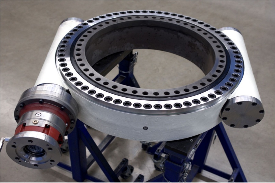
For crane applications requiring a related drive solution, review the available Truck Crane Slewing Drive options alongside the bearing interface. The bearing, drive gear engagement, motor or gearbox arrangement, and mounting structure should be reviewed as one assembly.
Choose replacement parts based on verified load paths, not appearance
The best replacement decision starts with a clear conclusion: select the bearing only after confirming the combined axial, radial, and overturning-moment conditions, plus the actual stiffness and bolt condition of the crane interface. This approach fits both preventive replacement and troubleshooting after abnormal movement or wear.
The reason is straightforward. The raceways carry rolling contact forces, while the mounting bolts and support structures maintain the clamped geometry that allows those raceways to work as intended. If any part of that chain is weak, the load distribution can change.
Luoyang Slewring Bearing Co., Ltd. has focused on slew bearing and slew drive research and development for more than 15 years, supporting more than 2,000 heavy-equipment projects. Our manufacturing facility includes six production lines and an annual capacity of 100,000 sets, supporting both standard and customized bearing requirements.
Before issuing an RFQ, assemble the crane drawing, bearing dimensions, bolt information, operating positions, load cases, and inspection findings. That package gives the supplier a practical basis to review whether the proposed bearing and mounting arrangement fit the real duty instead of only matching the old part number.
Request Your Custom Slew Drive or Bearing Spec
Tell us your load, speed, and environment — receive a tailored 100–5000 mm slewing drive or slewing bearing proposal with 3D drawings within 24 hours.
 WhatsApp

 +8613903880726