



What is a Truck Crane Slewing Bearing? It is the large rotational bearing installed between the crane chassis and the upper structure, allowing the boom, operator cab, counterweight, and lifting system to rotate around the vehicle center.
For an OEM designer or retrofit engineer, the main question is rarely whether a slewing bearing is needed. The question is whether a single-row design provides enough support for the working load spectrum, or whether a double-row design is justified by overturning moment, stiffness requirements, and duty cycle.
This decision affects more than bearing price. It can change turntable height, mounting bolt layout, frame reinforcement, assembly access, gearbox alignment, and long-term service risk. A bearing that fits the available envelope but lacks enough stiffness can lead to unwanted structural movement under load. A larger design can solve that issue, but it may add weight and require changes to the crane structure.

Start With the Load Path Rather Than the Bearing Catalog
A truck crane bearing does not carry one simple vertical load. It receives axial force from the upper structure, radial force from side loading and travel conditions, and overturning moment created when the boom lifts a load away from the crane centerline.
The overturning moment is often the deciding factor between row configurations. A long boom radius, heavy hook block, counterweight, and off-center load all increase the tendency of the upper structure to tip relative to the chassis. The bearing must transfer that tendency into the mounting structure without excessive movement or localized contact stress.
For this reason, selecting by outside diameter alone is not enough. Two bearings with similar diameters can behave differently because row arrangement, raceway geometry, rolling-element size, material selection, mounting arrangement, and internal clearance are different.
For a new crane design, begin by mapping the loads at the bearing mounting plane. For a retrofit, confirm whether the existing structural interfaces can accept a different bearing height, bolt circle, gear position, and mounting arrangement before comparing capacity values.
Inputs that should be defined before comparing designs
- Maximum axial load: Include upper structure weight, counterweight, boom weight, hook block, and the rated lifted load transferred through the slewing center.
- Maximum radial load: Consider side pull, boom deflection, travel vibration, and any horizontal load acting during crane operation.
- Overturning moment: Identify the worst rated lifting condition, boom radius, boom angle, and operating direction that create the largest tipping effect.
- Duty profile: Separate occasional maximum lifts from repetitive working cycles. A crane used for frequent loading operations needs a different assessment from a unit used mainly for intermittent service work.
- Mounting structure stiffness: Check the upper turntable and lower chassis ring. A well-sized bearing cannot compensate for distorted or weak mounting faces.
- Drive arrangement: Confirm pinion position, gear mesh requirements, drive torque, brake behavior, and available space for the slew gearbox or Slew Drive.
The practical conclusion is simple: use the full load case and structural interface as the selection basis. This approach fits both OEM design work and replacement projects. It does not apply when only a like-for-like service replacement is required and the original design data, mounting dimensions, and duty remain unchanged.
Compare Single-Row and Double-Row Designs for Crane Duty
Single-row and double-row bearing designs use different rolling-element arrangements to carry load. Neither is automatically better. The correct option depends on the relation between available space, moment demand, required stiffness, and the crane’s actual operating pattern.
| Selection Factor | Single-Row Design | Double-Row Design | Buyer Interpretation |
|---|---|---|---|
| Moment capacity | Generally suitable where overturning moment is moderate relative to bearing size and mounting support. | Generally offers a wider internal load-support arrangement, which can better resist higher overturning moment. | Choose double-row when the crane load case is governed by high tipping moment rather than simple vertical load. |
| Envelope size | Often supports a lower-profile or more compact arrangement, depending on raceway and gear design. | May require more axial height or a different structural envelope because of the added row arrangement. | Choose single-row when turntable height and package space are tightly controlled, provided calculations support it. |
| Stiffness | Can provide appropriate stiffness for many crane applications, but response depends heavily on bearing geometry and mounting rigidity. | Often provides higher resistance to rocking movement under combined load because loads are distributed across two rows. | Choose double-row when boom-end movement, turntable tilt, or gear-mesh stability is a major concern. |
| Typical truck-crane duty | Suitable for compact cranes, controlled duty cycles, and applications where design loads remain within the selected bearing rating. | Suitable for heavier upper structures, repeated lifting cycles, or operating conditions with greater combined axial, radial, and moment loading. | Match the row arrangement to the actual duty spectrum, not only the crane’s maximum advertised lifting capacity. |
| Structural integration | May simplify packaging where the crane frame has limited height available. | May demand stronger attention to upper and lower mounting-face flatness and ring support. | Review the bearing together with the turntable, chassis ring, bolts, and drive pinion. |
The industry observation is that catalogs often list bearing types and capacities, but the buyer still has to connect those data to truck-crane constraints. The row count alone does not prove suitability. A large single-row bearing can be appropriate in one crane, while a smaller double-row design may be preferred in another because stiffness and load distribution matter more than diameter.
A reasonable interpretation is that double-row designs become more attractive as combined loading and stiffness demands rise. That interpretation has limits. If the mounting structure is flexible, changing from single-row to double-row may not remove unwanted movement. The chassis and turntable must be assessed as part of the same mechanical system.
For applications requiring a higher load-oriented bearing arrangement, compare the design with a Heavy load slewing bearing specification rather than assuming that every double-row unit is suitable for the same duty.
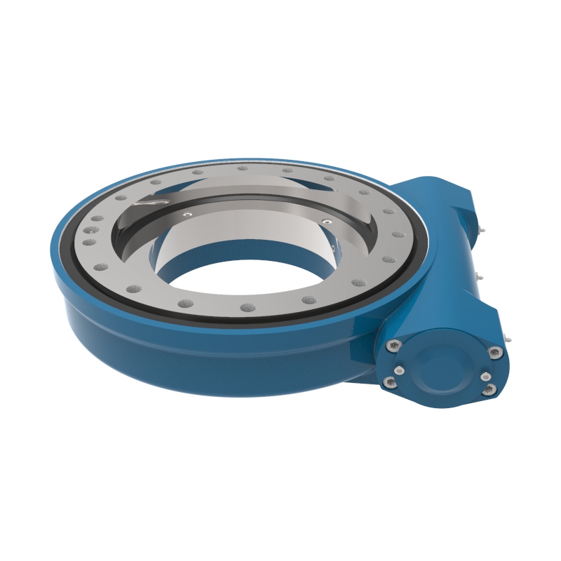
Use Stiffness and Mounting Conditions to Avoid a Misleading Selection
Moment capacity and stiffness are related, but they are not the same thing. Capacity addresses whether the bearing can carry a defined load condition. Stiffness concerns how much the system moves under load. For truck cranes, that movement can affect boom positioning, upper-structure feel, gear contact, and perceived stability.
A double-row design may improve resistance to tilting because the rolling elements act through separated load paths. However, the benefit can be reduced if the bearing is mounted on uneven surfaces, if the bolted joint loses preload, or if the supporting rings deform under working load.
Use the following checks before deciding that a row configuration is the root cause of crane movement.
- Check mounting-face condition: Inspect for dents, corrosion, weld distortion, paint buildup, and local gaps. Uneven support can create localized bearing loading.
- Review bolt arrangement: Confirm bolt grade, quantity, tightening method, tightening sequence, and inspection practice against the approved design. The bearing and bolts work as one joint.
- Inspect pinion engagement: Excessive rocking can change gear mesh during rotation. Check the relationship between the bearing gear, pinion, and slew drive mounting bracket.
- Separate bearing movement from frame movement: Measure or inspect the turntable and chassis support. A flexible support structure can appear to be a bearing problem.
- Confirm operating condition: Compare movement during unloaded rotation with movement under rated lifting conditions. The difference helps identify whether load-driven deformation is involved.
This is especially relevant for retrofit projects. If a crane shows rocking, noise, or uneven gear wear, replacing the bearing with a double-row model without reviewing the support structure can create a costly mismatch. The replacement may have a different height, bolt circle, gear location, or load path.
Luoyang Slewring Bearing Co., Ltd. can support bearing selection from application inputs through drawing review. Our engineering team works with detailed CAD modeling, tolerance verification, and material selection based on working conditions. For nonstandard interfaces, a Customized Slew Drive or matched bearing-drive arrangement may be more suitable than adapting a standard component without checking integration.
Request Your Custom Slew Drive or Bearing Spec
Tell us your load, speed, and environment — receive a tailored 100–5000 mm slewing drive or slewing bearing proposal with 3D drawings within 24 hours.
Match the Configuration to the Actual Crane Scenario
The following scenarios are not universal rules. They show how a buyer can translate technical conditions into a preliminary row-configuration decision before requesting a supplier proposal.
| Crane Scenario | Likely Starting Point | Why It Fits | What Could Change the Decision |
|---|---|---|---|
| Compact service crane with limited turntable height and intermittent lifting duty | Single-row design | A compact arrangement may better fit the available envelope when calculated axial, radial, and moment loads remain acceptable. | A long boom radius, repeated heavy lifts, or strict stiffness targets may justify a double-row review. |
| Truck crane with a heavy upper structure and frequent loading cycles | Double-row design | The arrangement may provide a better starting point where combined loading and resistance to rocking movement drive the design. | If chassis space, mounting height, or bearing support is restricted, a different bearing geometry may be required. |
| Existing crane bearing replacement with no structural changes allowed | Like-for-like configuration first | Maintaining the original interfaces reduces the risk of bolt, gear, height, and structural mismatch. | A design change is justified only after checking drawings, failure mode, load conditions, and frame capacity. |
| Crane with gear-mesh inconsistency during rotation | System inspection before redesign | Uneven mounting or support deformation may be the cause rather than insufficient bearing row count. | Verified bearing raceway damage or confirmed insufficient stiffness may support a new configuration. |
For an OEM platform, the best approach is to evaluate at least two bearing concepts during the layout stage: one optimized for package size and one optimized for stiffness and combined-load support. Compare both against the same load cases and mounting structure. This prevents a catalog choice from driving the crane architecture too early.
For a replacement project, start with the failed component’s condition. Raceway damage, gear wear, loose bolts, grease condition, mounting-face distortion, and operational history all provide useful evidence. Do not attribute every failure to insufficient bearing capacity. Misalignment, contamination, poor lubrication practice, or distorted mounting support can also shorten service life.
Ask Suppliers for Evidence That Supports the Design Decision
Supplier evaluation should move beyond a nominal model number. A useful technical proposal should show what data were used, what assumptions remain open, and where the supplier needs confirmation from the crane manufacturer or end user.
Buyer checklist for an RFQ or technical review
- Provide the installation drawing: Include mounting dimensions, bearing position, gear location, bolt pattern, available height, and interfaces with the turntable and chassis.
- Submit the load cases: List axial force, radial force, overturning moment, and the operating conditions that create each case.
- Describe the duty cycle: Explain whether lifting is occasional, repetitive, or continuous during a normal work shift.
- State environmental exposure: Identify moisture, dust, salt exposure, temperature conditions, and corrosion concerns that affect sealing and material choices.
- Define rotation requirements: Specify rotation speed, positioning needs, backlash sensitivity, and the planned drive system.
- Request inspection information: Ask how dimensional accuracy, gear condition, and load performance are checked before shipment.
- Confirm service requirements: Review lubrication access, inspection points, replacement procedure, spare-part needs, and warranty terms.
Luoyang Slewring Bearing Co., Ltd. operates an ISO 9001:2015 certified facility and provides CE marking for the European market. Our production site includes CNC machining centers and CMM three-coordinate inspection. These controls matter because dimensional accuracy and mounting interface consistency directly affect bearing installation and gear engagement.
Our quality process includes CMM three-coordinate inspection and dynamic load testing for every slewing bearing. We also provide a 2-year extended quality warranty and a 48-hour technical response for technical support. These are supplier-specific commitments, not an industry-wide benchmark, and buyers should still confirm that the selected design matches their own crane load cases.
For production planning, standard products have an MOQ of one set, while customized products have an MOQ of five sets. Sample orders are available for testing and evaluation. This can help OEM teams validate fit-up and rotation behavior before releasing a larger procurement order.
If your application has very high combined load requirements, it may also be useful to compare double-row concepts with Three-row Roller Slewing Bearings. That option is not automatically better for a truck crane, because it may introduce different packaging, weight, and integration requirements. It should be considered only when the calculated load case and crane architecture support the change.
Decide With Calculations, Drawings, and Inspection Evidence
The choice between single-row and double-row designs should be made from the crane’s actual combined loads and structural limits. Select a single-row arrangement when its calculated capacity and stiffness fit the duty, the package space is limited, and the mounting structure provides stable support. Select a double-row arrangement when higher overturning moment resistance and improved resistance to rocking movement are needed and the crane can accommodate the required interface.
The main uncertainty is often not the bearing itself. It is the accuracy of the load assumptions, the stiffness of the turntable and chassis, and the condition of the mounting joint. Better load data, structural analysis, and inspection of the existing machine can change the preferred option.
Luoyang Slewring Bearing Co., Ltd. has focused on slewing bearing and slew drive research and development for more than 15 years, supporting more than 2,000 heavy-equipment projects. For truck-crane projects, our team can review bearing drawings, working conditions, and integration requirements before recommending a suitable configuration.
Request Your Custom Slew Drive or Bearing Spec
Tell us your load, speed, and environment — receive a tailored 100–5000 mm slewing drive or slewing bearing proposal with 3D drawings within 24 hours.
 WhatsApp

 +8613903880726