



What is a slewing bearing raceway? It is the rolling path inside a bearing ring where balls or rollers carry axial load, radial load, and overturning moment between a fixed structure and a rotating structure.
For technical buyers and machine designers, the task is not simply choosing a bearing diameter. You need to match the raceway arrangement to the real load case, required stiffness, mounting space, rotation duty, and accuracy target. This guide explains how to compare slew bearings before you request drawings or specifications from a manufacturer.
A wrong raceway choice can create visible problems later. The machine may feel loose under offset load, rotate unevenly, show excessive gear backlash, or require a larger support structure than expected. The right choice starts with load direction and load distribution, not with a catalog photo.
Collect the load information before comparing bearing designs
Start by defining what the bearing must support during operation. A raceway cannot be selected from axial load alone because many rotating machines also apply radial force and overturning moment at the same time.
For example, a turntable with a centered vertical load behaves differently from a boom, crane, excavator attachment, or forestry grapple. In those applications, the working force acts away from the bearing center and creates a large moment load.
Prepare these inputs for the bearing supplier
- Axial load: The force acting parallel to the bearing axis, such as platform weight, payload, and downward working force.
- Radial load: The side force acting perpendicular to the bearing axis, such as wind, digging resistance, travel vibration, or side pull.
- Overturning moment: The tipping force created when a load is positioned away from the bearing center.
- Rotation requirement: State whether movement is intermittent positioning, continuous rotation, frequent reversing, or slow tracking.
- Required stiffness: Identify whether minor deflection is acceptable or whether the rotating structure must maintain a stable position.
- Mounting envelope: Provide available outside diameter, inside diameter, ring height, bolt circle, and gear location if space is already fixed.
- Operating environment: Include temperature exposure, dust, moisture, corrosion risk, and whether the unit is installed indoors, outdoors, offshore, or on mobile equipment.
The most common early mistake is reporting only the machine weight. That number does not show the supplier how far the load acts from the center, whether impact occurs, or whether the load direction changes during a working cycle.
When exact force data is not ready, provide the machine layout, the center of gravity position, the maximum working radius, and the intended operating motion. A manufacturer can then identify which missing input blocks final selection and which details can be refined during drawing review.
Luoyang Slewring Bearing Co., Ltd. can issue a technical proposal within 24 hours when the working condition and installation information are available. For a custom configuration, the engineering discussion should begin before bolt holes, gear direction, and mounting surfaces are frozen in the machine drawing.
Match four raceway arrangements to stiffness load direction and rotation requirements
The raceway layout determines how rolling elements share the load. Use the comparison below to choose a starting design, then verify the selection against the actual load spectrum and mounting arrangement.
| Raceway arrangement | Best load direction | Stiffness behavior | Rotation requirement it fits | Best-fit applications | When it may not apply |
|---|---|---|---|---|---|
| Four-point-contact ball | Combined axial, radial, and moment loads at moderate levels | General-purpose stiffness with one row of balls handling combined forces | Intermittent or regular rotation where compact structure matters | Turntables, light equipment, access platforms, and general rotating machinery | Not the first choice when very high moment load or very high structural stiffness is required |
| Double-row ball | Axial and radial loads with improved moment support compared with a single ball row | Higher stiffness because two ball rows spread load over a wider arrangement | Slow to moderate rotation where stable support is needed | Material handling equipment, truck-mounted equipment, and larger rotating platforms | May be unsuitable when the application needs the stiffness pattern or load separation of a roller design |
| Crossed-roller | Combined axial, radial, and moment loads requiring controlled rotation | High stiffness from rollers arranged in alternating directions | Precision rotation, indexing, positioning, and low-clearance motion | Automation equipment, medical platforms, inspection equipment, and precision turntables | Not the default choice for every heavy machine when load capacity and operating conditions point toward a larger roller raceway design |
| Three-row roller | High axial, radial, and overturning loads that need separate load paths | High stiffness because axial and radial forces are assigned to dedicated roller rows | Heavy-duty rotation under cyclic working loads | Excavators, cranes, mining machinery, and large industrial platforms | Usually unnecessary for light-duty equipment with modest loads and limited mounting space |
Choose a four-point-contact ball arrangement when the machine needs a compact bearing that can accept combined loads without requiring the highest possible stiffness. It fits a general rotating platform with manageable radial force and moment load. Do not use this as an automatic answer for a long boom or heavily offset payload without checking the moment demand.
Choose a double-row ball arrangement when the machine needs more stable support than a single-row ball design can provide, but the application does not justify a roller raceway. It is a practical option for equipment where combined loads are present and mounting height remains limited. It does not replace a heavy-duty roller design when severe cyclic loads dominate the duty.
Choose crossed rollers when rotational stiffness and controlled motion matter as much as load support. The alternating roller direction makes this arrangement suitable for applications where position accuracy and low deflection influence the machine result. It is less appropriate when the design brief is mainly maximum heavy-load capacity rather than controlled positioning.
Choose three-row rollers when high radial force, axial load, and overturning moment occur together. Separating these load directions into dedicated raceways supports heavy machinery layouts, especially where an offset load changes through the work cycle. Review the machine structure first, because a strong bearing cannot compensate for a weak mounting frame.
For product-level comparison, review Single Row Slewing Ring Ball Bearings, Crossed Roller Slewing Bearings, and Three-row Roller Slewing Bearings alongside your load drawing.
Request Your Custom Slew Drive or Bearing Spec
Tell us your load, speed, and environment — receive a tailored 100–5000 mm slewing drive or slewing bearing proposal with 3D drawings within 24 hours.
Use a step-by-step selection process instead of choosing by bearing size
Follow the sequence below to move from a machine concept to a raceway recommendation. Each step removes a selection risk that cannot be solved by outside diameter alone.
- Draw the bearing center and load points. Mark the rotation axis, platform weight, payload center, actuator force, and external working force. A successful drawing shows how far each force acts from the center. If all loads are shown at the center, the overturning moment has been missed.
- Separate static and working conditions. Record the parked condition, normal operating condition, maximum working condition, and any reversing or impact event. The bearing must be assessed against the condition that governs the load case, not just normal operation.
- Identify the dominant load. Decide whether the main concern is axial force, radial force, overturning moment, or controlled rotation. This points to the raceway arrangement that deserves first review.
- Check the required structural stiffness. Review whether bearing deflection could change gear mesh, sensor alignment, boom position, tool location, or safety clearance. High stiffness needs often move the choice from ball raceways toward crossed-roller or multi-row roller arrangements.
- Confirm the rotation pattern. State the rotation angle, frequency, direction changes, and whether the machine holds position under load. Continuous motion, indexing, and slow tracking can have different design priorities.
- Review the mounting structure. Check that the upper and lower mounting faces are sufficiently supported and that the bolt pattern can be designed around the selected ring. A bearing installed on distorted mounting faces may show uneven load sharing even when the bearing type is correct.
- Send the load table and installation drawing for verification. Ask the supplier to review raceway type, ring dimensions, gear arrangement, material choice, sealing need, and inspection requirements together.
Do not choose a larger ring only because the machine has a larger platform. A wide platform with centered light load may not need the same raceway arrangement as a compact machine with a long offset boom. The force path decides the bearing design.
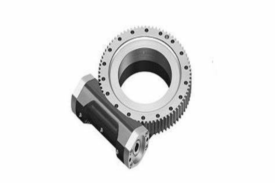
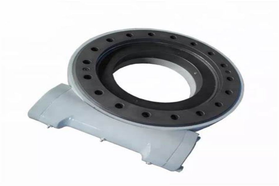
For machines that need an integrated rotation and drive unit, the bearing selection also affects worm gear engagement, torque transmission, and mounting layout. A Slew Drive may be more suitable than a separate bearing-and-drive arrangement when the application needs a packaged turning solution.
Check failure risks that point to the wrong raceway choice
Early inspection and design review can reveal whether the selected arrangement is mismatched to the application. The table below links visible machine symptoms to a practical recovery action.
| Observed issue | Likely selection or installation reason | What to review |
|---|---|---|
| Platform feels unstable under an offset payload | Moment demand exceeds the stiffness expected from the selected raceway arrangement | Recalculate the offset load condition and compare double-row ball, crossed-roller, and three-row roller options |
| Rotation becomes uneven at certain positions | Mounting support may be uneven, or the load distribution may be more severe than assumed | Inspect mounting faces, bolt layout, support frame rigidity, and actual working load positions |
| Gear mesh changes during operation | Bearing or support structure deflection affects the drive relationship | Review overturning moment, structural stiffness, gear location, and drive mounting arrangement |
| Precision position is difficult to repeat | The application may need a higher-stiffness arrangement or tighter system-level control | Check crossed-roller suitability, drive backlash, encoder arrangement, and machine frame movement |
| Corrosion or contamination enters the bearing area | Environmental protection was not matched to the installation site | Specify sealing, lubrication access, coating needs, and exposure to dust, water, or salt conditions |
A frequent purchasing error is treating the raceway choice as separate from the mounting structure. The bearing, bolts, upper frame, lower frame, and drive system work as one assembly. If the frames bend, the rolling elements cannot share load as intended.
Another error is requesting a standard part before confirming whether the gear, bolt circle, raceway type, and sealing level fit the machine. Standard product orders can begin from one set, while customized product orders have a five-set minimum at Luoyang Slewring Bearing Co., Ltd. Samples are available for testing and evaluation when the project needs a physical fit check.
Material selection should also follow working conditions. The company uses ductile cast iron, alloy steel, stainless steel, and forged alloy steel according to load, speed, and environment rather than applying one material choice to every machine.
Verify the proposed design before releasing production drawings
A useful bearing proposal should show more than a model number. Confirm that the supplier has reviewed the raceway arrangement against your axial, radial, and moment loads, plus the mounting dimensions and rotation requirement.
Buyer verification checklist
- Does the proposal identify the selected raceway type and explain why it fits the dominant load direction?
- Have maximum offset load and overturning moment been included, not only machine dead weight?
- Does the drawing show the inner ring, outer ring, gear position, bolt circles, and mounting dimensions?
- Has the supplier confirmed the intended rotation pattern and environmental exposure?
- Is the selected material aligned with load, speed, and corrosion conditions?
- Are inspection steps defined before shipment?
- For a driven assembly, has the bearing been reviewed together with the drive and gear arrangement?
Luoyang Slewring Bearing Co., Ltd. operates an ISO 9001:2015 certified facility and provides CE marking for the European market. Its production facility includes CNC machining centers and CMM three-coordinate inspection, which are relevant when the bearing must match a defined drawing and mounting interface.
The company states that every slewing bearing passes CMM three-coordinate inspection and dynamic load testing. Factory audit reports are available on request, which gives procurement teams a documented route for supplier qualification before a production release.
For a heavy load application, compare the proposed configuration with the requirements of a Heavy load slewing bearing rather than assuming a light-duty ball design will scale upward. For compact equipment with modest loads, a Light Load Slewing Bearing may provide a more suitable starting point.
Apply the raceway choice to the machine type that changes the answer
Application differences can change the recommended arrangement even when two machines have similar overall weight. The deciding factor is how each machine applies force during work.
Crane and boom equipment: Start with overturning moment because the payload acts at a distance from the rotation center. A roller arrangement is often worth reviewing when the boom radius, cyclic loading, and required support stiffness are the governing conditions. A simple ball arrangement may still fit a lighter platform, but only after the maximum working radius is checked.
Automation turntables: Start with position stability and repeatable movement. Crossed rollers are often a logical design candidate when the table supports a tool, fixture, sensor, or inspection part that cannot tolerate excessive movement. Manchester, UK automation equipment manufacturer ordered 100 units of SP-I 0841-32.1 for automated turntable systems, showing the relevance of matching rotation components to application duty.
Excavators and mining equipment: Start with combined loading, shock exposure, and cyclic moment. A multi-row roller approach should be evaluated when the attachment creates changing radial and moment forces. An Australian heavy equipment manufacturer selected HWE21-94-25HR.1 double worm slew drives for mining excavators, where the drive arrangement supports the demanding equipment category.
Solar trackers: Start with controlled tracking, environmental exposure, and drive integration. The bearing system must support the panel structure while the drive maintains the required rotation movement. South American solar projects in Brazil, Argentina, and Chile used SP-I 0229 spur gear slew drives for single-axis trackers, with reported energy yield improvement up to 40% in those projects.
The final result should be a raceway choice that matches the actual load path, a mounting drawing that supports it, and an inspection plan that verifies the delivered part. Once those three items agree, the buyer can request a drawing, sample, or production quotation with fewer technical gaps.
Request Your Custom Slew Drive or Bearing Spec
Tell us your load, speed, and environment — receive a tailored 100–5000 mm slewing drive or slewing bearing proposal with 3D drawings within 24 hours.
 WhatsApp

 +8613903880726