



Executing a slew bearing replacement procedure correctly is about more than just swapping an old part for a new one. A frequent cause of premature bearing failure isn’t a manufacturing defect but an installation error that introduces unseen stresses. When a bearing is installed on an uneven surface or torqued improperly, the precision-ground raceway can distort, leading to binding, accelerated wear, and catastrophic failure of your equipment.
My name is Lewis, and with over 30 years in heavy machinery design, I've seen firsthand how a flawed installation can ruin a perfectly good component. This guide provides a detailed, step-by-step process to ensure your replacement is done right, protecting your investment and maximizing the operational life of your new bearing. We will cover everything from initial preparation to the critical steps that prevent misalignment.
Pre-Replacement Inspection and Preparation Checklist
Before you even think about loosening a bolt, proper preparation is essential. Rushing this stage is a common mistake that leads to extended downtime and installation problems. A systematic approach ensures you have the right parts, tools, and safety measures in place.
Use this checklist to confirm your readiness:
- Gather Documentation: Secure the Original Equipment Manufacturer's (OEM) service manual for your specific machine. This document contains critical information, including specified bolt torque values, lubrication types, and lifting points. Have the technical sheet for the new Slewing Bearing on hand.
- Verify the New Bearing: Unbox the new bearing and inspect it for any signs of damage that may have occurred during shipping. Cross-reference the part number with your order. Locate the "soft zone" marking (often an "S" or a paint mark), which should be positioned in the area of minimum load during installation.
- Prepare Essential Tools: Ensure you have a calibrated torque wrench, a complete socket set, feeler gauges, a straight edge, lifting chains or straps rated for the load, and appropriate cleaning supplies (degreasers, lint-free cloths).
- Implement Safety Protocols: Follow all standard lockout/tagout (LOTO) procedures to de-energize the equipment. Mechanically secure the rotating superstructure against any possible movement before beginning work.
At Luoyang Slewring Bearing, we ensure every component leaves our ISO 9001:2015 certified facility ready for service. Each bearing undergoes a rigorous CMM three-coordinate inspection to verify dimensional accuracy, part of a military-grade quality control process that keeps our failure rate below the 0.5% industry standard.
Preventing Raceway Distortion: Surface Prep and Tightening
The single most critical phase of a slew bearing replacement procedure is the installation of the new unit. This is where microscopic errors in flatness or uneven clamping forces can permanently damage the bearing before it ever sees a single operational hour. The goal is to mount the bearing so that it remains perfectly flat and round, without any external stress distorting its precise geometry.
Here’s how to achieve that by focusing on three key areas: controlled lifting, mounting surface preparation, and the bolt tightening sequence.
1. Controlled Lifting and Placement
The rotating superstructure must be fully and independently supported by a crane or hydraulic jacks. The new bearing should never be used to lift or level the structure. When lowering the bearing into place, do so slowly and evenly. Use the alignment marks you made during removal to guide it into the correct orientation.
2. Mounting Surface Preparation
The mounting surfaces on both the stationary base and the rotating structure must be perfectly clean, flat, and free of defects. Any imperfection will transfer stress directly into the bearing rings.
- Cleaning: Scrape off all old sealant, rust, and paint. Use a solvent to remove any residual grease or oil. The surface must be bare metal.
- Inspection: Check for and remove any burrs, nicks, or weld spatter. Even a small high spot can act as a fulcrum, bending the bearing race as the bolts are tightened.
- Flatness Check: Use a precision straight edge and feeler gauges to check the flatness of both mounting surfaces. Check radially and across the diameter in several locations. Consult the OEM manual for the maximum allowable deviation; if not specified, a general tolerance is typically around 0.05 mm (0.002 inches). Mark any high or low spots for remediation.
3. Cross-Pattern Bolt Tightening Sequence
Uneven bolt tightening is a primary cause of raceway distortion. Simply tightening bolts one after another in a circle will warp the bearing ring. The correct method involves applying torque gradually and evenly across the entire bolt circle using a star or cross pattern.
Follow this multi-pass procedure for both the inner and outer ring bolts:
| Step | Action | Purpose |
|---|---|---|
| 1. Hand-Tighten | Install all bolts and tighten them by hand until they are snug. The bearing should sit flat without any gaps. | Ensures all bolts are properly threaded and the bearing is seated correctly before applying torque. |
| 2. First Pass (30%) | Using a calibrated torque wrench, tighten each bolt to 30% of the final specified torque value. Follow a star pattern (e.g., 1, 6, 2, 7, 3, 8...). | Applies a light, even clamping force to settle the bearing without distortion. |
| 3. Second Pass (70%) | Repeat the star pattern, tightening each bolt to 70% of the final torque value. | Brings the connection closer to the final clamping load in a controlled manner. |
| 4. Final Pass (100%) | Repeat the star pattern one last time, tightening each bolt to 100% of the specified torque. | Achieves the final, correct clamping force required for secure operation. |
| 5. Final Check | After the final pass, go around the bolt circle one more time in sequence to verify that all bolts are at the final torque value. | Confirms that tightening one bolt did not slightly loosen an adjacent one. |
This methodical process ensures the clamping force is distributed evenly, preserving the bearing's internal geometry and preventing the creation of tight spots that lead to rapid wear.
Request Your Custom Slew Drive or Bearing Spec
Tell us your load, speed, and environment — receive a tailored 100–5000 mm slewing drive or slewing bearing proposal with 3D drawings within 24 hours.
Final Verification and Commissioning
Once the new bearing is fully installed and torqued, a few final checks are necessary to confirm the installation was successful before returning the equipment to full service. These steps validate that the bearing is properly aligned and functioning as intended.
1. Check Rotational Torque: Before connecting the drive motor or pinion, rotate the bearing by hand or with a lever for at least two full rotations. The movement should be smooth and consistent. If you have a baseline rotational torque reading from the new bearing's spec sheet, you can use a torque wrench to measure it. A significant spike in torque indicates a potential alignment or contamination issue.
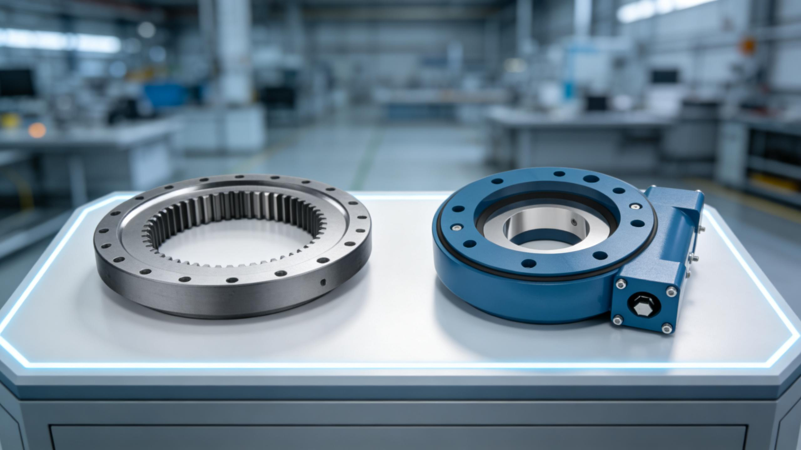
2. Verify Gear Backlash: For geared bearings, use a feeler gauge or dial indicator to measure the backlash between the slew bearing gear and the drive pinion. Check this measurement at a minimum of four points around the bearing's circumference. Ensure the backlash is within the range specified by the OEM. This is the same precision we deliver for clients like the South Korean port equipment manufacturer, whose WEA series Slew Drive units require ≤0.15° tracking precision.
3. Lubricate the Bearing: Using the recommended grease type, pump grease into the fittings until you see fresh grease purging from the seals. This ensures all air pockets are removed and the raceway is fully protected. Rotate the bearing several times during lubrication to distribute the grease evenly. Also, apply an appropriate open-gear lubricant to the gear teeth if applicable.
4. Conduct a Test Run: Re-engage the drive system and operate the equipment through its full range of motion without any load. Listen for any unusual grinding, popping, or scraping sounds. Check for any binding or hesitation in movement. If the no-load test is successful, proceed with a light-load test before returning to full operational capacity.
Common Installation Mistakes to Avoid
Over my career, I’ve seen a few recurring errors that account for the majority of installation-related failures. Avoiding them is simple if you know what to look for. Many of these issues can damage even the most robust Heavy load slewing bearing.
-
Mistake: Using an Impact Wrench for Final Torque.
Why it's a problem: Impact wrenches are imprecise and deliver uneven torque, which is the fastest way to warp a bearing ring.
Solution: Only use a calibrated, manual torque wrench for the final tightening passes. An impact wrench can be used to snug the bolts initially, but never for final torque. -
Mistake: Neglecting to Re-Check Bolt Torque.
Why it's a problem: Gaskets and metal surfaces can settle after initial loading, causing a loss of bolt preload. Loose bolts can lead to bearing movement and eventual failure.
Solution: After a short period of initial operation (e.g., 8-10 hours), re-check the torque on every bolt while the equipment is safely shut down. -
Mistake: Storing the Bearing Improperly Before Installation.
Why it's a problem: Storing a bearing vertically on its edge can cause the rings to go out of round. Storing it in a damp environment can lead to corrosion.
Solution: Always store slew bearings flat (horizontally) in a clean, dry, and vibration-free environment. Keep it in its original packaging for as long as possible. -
Mistake: Damaging Seals During Installation.
Why it's a problem: A nicked or torn seal allows contaminants like dirt and water to enter the raceway, quickly destroying the bearing from the inside.
Solution: Be careful with tools, pry bars, and lifting chains around the bearing. Never use the seals as a lifting or leverage point.
By following a disciplined slew bearing replacement procedure, you ensure that the component's engineered lifespan is fully realized. This approach has been validated across more than 2,000 heavy-equipment projects we've supported, from double worm slew drives on mining excavators in Australia to spur gear drives on solar trackers in South America. If you require technical assistance or need a reliable replacement bearing engineered for your specific application, our team is ready to provide a proposal within 24 hours.
Request Your Custom Slew Drive or Bearing Spec
Tell us your load, speed, and environment — receive a tailored 100–5000 mm slewing drive or slewing bearing proposal with 3D drawings within 24 hours.
 WhatsApp

 +8613903880726