



As a design engineer with over three decades in heavy machinery, I’m often asked this question. The short answer is: not always, but when they are, they are non-negotiable. Choosing a standard slew drive for an application with high shock loads is one of the fastest ways to cause catastrophic failure. The key is to accurately assess your application’s operational demands to determine which slew drive features are truly required.
A slew drive is a gearbox designed to handle axial, radial, and tilting moment loads. It functions as a compact rotational unit. However, not all loads are created equal. A smooth, predictable load, like that on a solar tracker slowly following the sun, is vastly different from the sudden, jarring impacts experienced by a mining excavator or a forestry grapple. Understanding this distinction is the first step in proper specification.
Defining the Boundary: When Shock Resistance Becomes Essential
The decision to specify a shock-resistant Slew Drive isn't based on a single parameter. It’s determined by the intersection of load type, duty cycle, and the operating environment. An application crosses the boundary into "shock-prone" territory when it experiences frequent, high-energy events that exceed the drive's standard dynamic load capacity. These events can include sudden starts and stops, external impacts, or high levels of vibration.
In my experience, engineers sometimes miscalculate this boundary by focusing solely on the maximum static torque. A drive might be able to hold a heavy load in a static position, but it may not be able to withstand the dynamic forces of moving that same load erratically. The table below outlines the key differences between a standard duty cycle and one that demands shock-resistant features.
| Parameter | Standard Duty Application (e.g., Solar Tracker, Light Automation) | Shock-Prone Application (e.g., Excavator, Marine Crane, Forestry Grapple) |
|---|---|---|
| Load Type | Primarily static or slowly changing dynamic loads. Smooth, predictable motion. | High, unpredictable impact loads; frequent acceleration/deceleration; significant vibration. |
| Starting/Stopping Torque | Low to moderate. Motion is ramped up and down smoothly. | High peak torque on startup and braking. Sudden, jarring stops are common. |
| External Forces | Minimal. Primarily consists of wind or gentle operational loads. | Frequent external impacts from digging, lifting, or environmental factors (e.g., wave action on a shipboard crane). |
| Duty Cycle | Continuous or intermittent with low frequency. | High-frequency, heavy-duty cyclic loading. |
| Required Precision | Moderate to high, but under controlled motion. | High precision must be maintained despite external shock and vibration. Example: Our WED Slew Drive models for forestry equipment maintain ≤0.13° precision under heavy loads. |
| Failure Consequence | Production loss, downtime. | Catastrophic equipment failure, potential safety hazards, significant financial loss. |
Key Slew Drive Components for High-Impact Environments
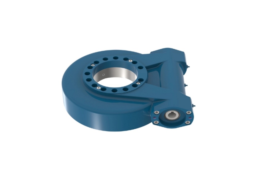
When an application is identified as shock-prone, several core components of the slew drive must be enhanced. Simply using a larger standard drive is often an inefficient and ineffective solution. True shock resistance is engineered into the unit's design and material composition.
1. Reinforced Housing and Structure
The housing is the drive's backbone. For shock-duty applications, we move beyond standard cast iron to materials like high-strength ductile cast iron or even forged steel. The housing design will incorporate thicker walls and additional external ribbing to increase rigidity and prevent cracking or deformation under sudden impact.
2. Hardened Gear and Bearing Raceways
The point of contact between the worm and the Slewing Bearing is a critical failure point. In a shock-resistant drive, raceways undergo a deeper induction hardening process. This creates a more substantial hardened layer that can absorb impact energy without brinelling (denting) or spalling. The core of the material remains ductile to prevent catastrophic fracture.
3. High-Strength Worm Gear and Shaft
The worm itself must be made from a superior material, typically a high-strength forged alloy steel like 42CrMo, which is then precision-ground and heat-treated. This ensures the gear teeth can withstand the immense shearing forces during a shock event. For extreme applications, such as the HWE21 double worm slew drives we supplied to an Australian heavy equipment manufacturer for mining excavators, a Double Worm Slew Drive design can be used to distribute the load across more gear teeth, increasing torque output and shock resistance.
4. Enhanced Sealing Systems
Shock-prone environments are often also harsh environments—dusty, wet, or corrosive. A standard seal can fail under high vibration or pressure changes, allowing contaminants to enter and destroy the raceways. We equip our heavy-duty drives with sealing systems rated up to IP66, ensuring protection against powerful water jets and dust ingress. This was a critical requirement for the SP-I series slew drives used in utility-scale solar trackers at desert sites for a US renewable energy client, where IP65 was essential.
Request Your Custom Slew Drive or Bearing Spec
Tell us your load, speed, and environment — receive a tailored 100–5000 mm slewing drive or slewing bearing proposal with 3D drawings within 24 hours.
Common Mistakes in Specifying Drives for Cyclic and Impact Loads
Overlooking the nuances of shock loading during the design phase can lead to costly and dangerous failures. Having led the mechanical design for over 200 heavy-equipment projects, I have seen a few common missteps that engineers should avoid.
- Mistake 1: Focusing Only on Static Load Capacity. The most frequent error is selecting a drive based on its holding torque. A drive's ability to resist a static load says very little about its ability to handle dynamic, jarring forces. Always analyze the full load spectrum, including peak dynamic torque and impact energy.
- Mistake 2: Underestimating Environmental Vibration. Continuous, high-frequency vibration from an engine or work process (like drilling or digging) can be as damaging as a single large impact. This vibration can lead to fretting corrosion in the bearing and premature gear wear. The mounting structure must be sufficiently rigid to dampen these effects.
- Mistake 3: Ignoring the Self-Locking Characteristic. For applications like cranes and manlifts, a strong self-locking ability is a critical safety feature. It prevents the load from back-driving the gearbox in case of power loss. Our WEA series slew drives, used by a South Korean port equipment manufacturer for crane systems, were selected specifically for their strong self-locking and ≤0.15° tracking precision.
- Mistake 4: Choosing an Inadequate Service Factor. The service factor is a multiplier applied to your calculated loads to account for uncertainties and operational severity. For smooth, 8-hour-a-day operations, a service factor of 1.0 or 1.25 might be sufficient. For heavy-duty applications with frequent shocks, a service factor of 2.0 or higher is often necessary. Failing to apply an appropriate service factor is a gamble on your equipment's reliability.
Verifying Shock Resistance: What to Ask Your Supplier
When you are sourcing a slew drive for a demanding application, you need to be confident that it meets the required specifications. As a manufacturer, we welcome detailed technical questions because it shows the client is serious about reliability. Here is what you should ask to verify the quality and suitability of a proposed drive.
First, request material certifications for the critical components: the worm, the slewing ring, and the housing. The supplier should be able to provide documentation proving the use of specified materials like forged alloy steel. At Luoyang Slewring Bearing Co., Ltd., our process is transparent, and we select materials based on a thorough analysis of the customer's working conditions.
Second, inquire about the quality control and testing procedures. A claim of "high quality" is meaningless without proof. Ask if each unit undergoes inspection and testing. Our facility is ISO 9001:2015 certified, and we follow a military-grade quality control process. Every single Slew Drive Quality Control check includes CMM three-coordinate inspection of critical dimensions and dynamic load testing to simulate real-world conditions. This rigorous testing allows us to achieve a failure rate below the 0.5% industry standard.
Finally, discuss the warranty and technical support. A supplier confident in their product's durability will back it with a solid warranty. We offer a 2-year extended quality warranty and a 48-hour technical response commitment. If a manufacturing defect is confirmed, we provide a free replacement. This level of support provides peace of mind that you are not just buying a component, but a reliable, long-term solution.
Ultimately, the decision to use shock-resistant slew drive features comes down to a thorough risk-versus-cost analysis. While these features increase the initial investment, they prevent far greater costs associated with downtime, repairs, and safety incidents in demanding applications. When in doubt, partner with a manufacturer whose engineering team can help you analyze your application and specify the right drive for the job. Our team can provide a detailed technical proposal within 24 hours to get your project started on the right foundation.
Request Your Custom Slew Drive or Bearing Spec
Tell us your load, speed, and environment — receive a tailored 100–5000 mm slewing drive or slewing bearing proposal with 3D drawings within 24 hours.
 WhatsApp

 +8613903880726