



How do you turn machine operating data into a usable slew drive requirement? That is the question behind successful slew drive applications, especially when an equipment builder has a basic load estimate but no clear record of starts, rotation angle, dwell time, shock, or weather exposure.
A slew drive combines a slewing bearing, worm or spur transmission, housing, and mounting interfaces into a compact rotary system. The right unit is not simply the one with the largest published capacity. It must match how the machine actually moves, stops, holds position, and faces its working environment.
For OEM engineers, the target outcome is practical: create a duty-cycle record that a supplier can review before recommending a standard Slew Drive or a customized unit. Luoyang Slewring Bearing Co., Ltd. supports this process with technical proposals within 24 hours, while customized product orders start from a minimum order quantity of 5 sets.

Start With Machine Behavior Instead of Product Size
Begin with the machine’s real movement pattern. A drive selected from mounting size, motor size, or a previous model number alone can miss the operating condition that causes early wear, poor positioning, or unexpected heating.
Record one representative operating hour and one representative working day. If the machine has several modes, such as travel, lifting, positioning, and idle holding, document each mode separately. A solar tracker and a forestry grapple may both rotate through limited angles, but their loading events are very different.
Collect the inputs that change selection
- Driven load and load position: Identify the rotating structure, mounted payload, center-of-gravity offset, and the direction in which external force reaches the drive.
- Starts per hour: Count every motor start, reversal, and repeated positioning command. Frequent short moves can impose a different demand than continuous slow rotation.
- Rotation angle per move: Record whether the machine turns through a small index angle, a partial sweep, or repeated larger rotations.
- Dwell time: Note how long the unit holds position between moves. Dwell may allow cooling, but it can also mean the drive spends long periods resisting wind, gravity, or a held load.
- Shock events: Identify sudden loading from bucket impact, grapple closure, vehicle movement, emergency stopping, or a load reaching a mechanical stop.
- Outdoor exposure: List rain, dust, salt air, solar heat, washdown, and temperature changes. Outdoor protection cannot be decided from location alone; exposure must be tied to how the machine is installed and maintained.
- Positioning expectation: Define whether the task is broad orientation, repeatable indexing, stable tracking, or controlled steering.
Do not wait for every detail before requesting an engineering review. The first version can use measured machine data, drawings, expected payload, and operating assumptions. However, missing shock information or an unknown load offset can block final selection because both can change the load transmitted into the bearing and gear set.
A useful starting document is a one-page operating sheet. Include a machine drawing, mounting arrangement, motor type, available space, target motion, and expected environment. This gives the supplier an engineering basis rather than a request for “the nearest equivalent.”
Use a Duty-Cycle Matching Method Before Selecting the Drive
The most useful method links five operating facts: starts per hour, rotation angle, dwell time, shock events, and outdoor exposure. The conclusion is not a generic product category. It is a duty profile that shows which parts of the drive need added attention: transmission loading, bearing support, sealing, corrosion protection, positioning stability, or mounting stiffness.
Build the profile in the order below. Each step depends on the prior one, because rotation frequency without the load condition does not show the whole duty.
- Count starts and reversals. Separate normal starts from emergency stops and frequent direction changes. A high count points to repeated gear engagement and motor-control events; it fits indexing tables, access equipment, and automation systems. It does not by itself prove that a larger drive is needed, because the rotation angle and applied load may still be modest.
- Measure rotation angle per command. Record the actual movement, not the full possible travel of the machine. Small repeated angles often create repeated contact in a limited gear zone, while wider sweeps distribute motion differently. This step matters for turntables, grippers, and trackers, but it cannot replace a load and moment review.
- Time the dwell period. Mark whether the unit rests unloaded, holds a raised structure, resists wind, or remains under off-center payload. Long dwell under load means holding behavior matters. Long dwell with no external force is less demanding, although outdoor contamination may remain a concern.
- Classify shock events. Identify their source and whether they occur during rotation, at the end of travel, or while stationary. Repeated shock calls for review of the mounting structure and load path, not just the drive model. A larger drive cannot correct loose mounting bolts, a flexible frame, or an external mechanical stop that is struck at speed.
- Map outdoor exposure. Identify dust, rain, marine air, and washdown near seals and mounting faces. Select protection based on the actual exposure and service plan. Higher protection is not a substitute for correct installation or regular inspection.
- Review the combined result. Send the duty profile with layout drawings and load information. A suitable proposal should state the assumed duty and identify any conditions that still require confirmation.
| Duty-cycle factor | What to record | Selection implication | Common failure reason |
|---|---|---|---|
| Starts per hour | Normal starts, reversals, emergency stops | Checks repeated transmission engagement and motor-control demand | Counting only total operating hours |
| Rotation angle | Actual angle for each command | Shows whether motion is small-angle indexing, sweep motion, or tracking | Using maximum machine travel instead of normal travel |
| Dwell time | Time between moves and held-load condition | Checks holding demand, heat recovery time, and external-force exposure | Calling all idle time “unloaded” |
| Shock events | Source, timing, and repeat frequency | Triggers review of bearing, gearing, housing, and machine frame | Ignoring impacts that occur while the drive is stopped |
| Outdoor exposure | Dust, rain, salt air, washdown, and service access | Guides sealing and corrosion-protection requirements | Specifying indoor protection for equipment stored outside |
Successful progress means the profile describes a real operating cycle that production, service, and engineering teams all recognize. If they disagree on how often the machine moves or when it sees shock, pause selection and observe an operating machine or review controller logs. Guessing at this stage often creates the wrong design target.
Translate the Duty Profile Into Drive Architecture and Protection
Once the duty record is complete, match it to drive architecture. A Worm Gear Slew Drive is often considered where controlled rotation and holding behavior are required. The final choice still depends on load direction, motion pattern, mounting arrangement, motor interface, and environmental exposure.
For higher resistance to external turning forces or a demand for more balanced drive input, a Double Worm Slew Drive may be the better route. This fits certain heavy-duty steering, excavating, and attachment conditions. It does not remove the need to verify the equipment frame, bolt pattern, and load path.
Spur gear designs can suit applications where the motion and transmission arrangement favor that configuration. They should be reviewed as part of the full machine design, rather than treated as interchangeable with a worm arrangement. The operating record remains the decision source.
| Application condition | Recommended selection focus | Reasoning | Where this does not apply alone |
|---|---|---|---|
| Slow outdoor solar tracking with long dwell periods | Environmental sealing, corrosion resistance, tracking requirement, and held wind load | The drive spends substantial time holding the structure between adjustment movements | It does not define a drive size without the tracker structure and external load data |
| Repeated automated indexing | Starts, reversal pattern, rotation angle, and repeatability expectation | Frequent short moves can place demand on gears, bearing support, and control behavior | It does not justify high outdoor protection for a protected indoor cell |
| Forestry attachment with irregular impacts | Shock source, load path, housing support, and mounting stiffness | Impact events may govern selection more than average rotation time | It does not mean every attachment needs the same dual-worm configuration |
| Access platform with held elevated load | Holding condition, off-center load, start-stop sequence, and safety-related machine design review | The drive may hold position as well as rotate the platform | It does not replace the complete machine safety assessment |
Environmental requirements should be written in the same specification as the motion data. Luoyang Slewring Bearing Co., Ltd. supplies slew drives with protection up to IP66 and anti-corrosion protection up to C4H, selected according to the stated working environment. These levels are options for suitable applications, not default requirements for every machine.
Material selection also follows the duty. Ductile cast iron, alloy steel, stainless steel, and forged alloy steel can be selected according to load, speed, and environment. A material request without operating data is incomplete because corrosion resistance, structural demand, and cyclic loading do not always point to the same choice.
Request Your Custom Slew Drive or Bearing Spec
Tell us your load, speed, and environment — receive a tailored 100–5000 mm slewing drive or slewing bearing proposal with 3D drawings within 24 hours.
Apply the Method to Four Real Equipment Profiles
Application names alone are not enough. The profiles below show how the same five duty-cycle factors lead engineers toward different questions and different selection priorities.
Single-axis solar trackers
Solar tracker duty commonly involves controlled movement followed by long dwell periods outdoors. The selection record should identify expected tracking movement, wind exposure while parked or tracking, contamination risk, maintenance access, and the needed positioning result.
For example, SP-I 0229 spur gear slew drives were supplied for single-axis solar projects in Brazil, Argentina, and Chile, where the reported result was energy yield improvement of up to 40%. That project result should not be treated as a universal forecast, because site layout, tracker design, weather, controls, and panel configuration affect energy output.
A separate U.S. renewable energy equipment manufacturer ordered 50 units of SP-I 0841 for utility-scale solar tracker systems, specified with IP65 protection for desert sites. The relevant lesson is to document actual dust exposure and sealing needs, rather than assume every solar site has the same conditions. Review the available SP-I Slew Drive options after the tracker duty record is complete.
Access platforms and manlifts
Access equipment should be assessed for start-stop movement, platform position, held load, and outdoor storage. The drive may make short positioning movements, then hold a structure exposed to gravity and wind. That profile makes dwell condition as meaningful as active rotation time.
Record whether the platform turns mainly under low load, under a raised load, or during repeated work cycles. Also identify any end-of-travel event that could create a shock load. A drive choice cannot stand in for full machine safety design, control logic, or structural verification.
Forestry grapples and heavy attachments
Forestry equipment often combines irregular rotation with impact, contamination, and high external loads. A duty record should mark grapple closure, contact with logs, vehicle motion, transport vibration, and the point at which the attachment changes direction.
A forestry equipment manufacturer in British Columbia ordered 30 WED14-86-25BHR.5 double worm slew drives for grapple machines, with stated positioning precision of no more than 0.13 degrees. That case supports the need to define position requirements alongside shock and load conditions. It does not establish the same precision requirement for every forestry attachment.
Industrial automation turntables
Industrial turntables often have more predictable movement but can create many starts and reversals. Record the index angle, cycle sequence, payload position, dwell time for welding or assembly, and whether the turntable is indoors or exposed to contaminants.
A Manchester automation equipment manufacturer ordered 100 SP-I 0841-32.1 units for automated turntable systems. This example shows that repeatable factory motion still needs a defined duty profile. An indoor automation system may need a different protection approach than an outdoor machine, even if both rotate through similar angles.
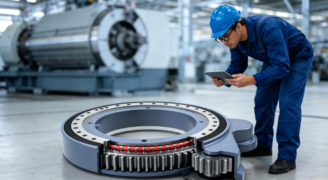
Check the Proposed Drive Against the Machine Before Release
Before releasing a purchase order, compare the supplier proposal against the original duty sheet. The goal is not only to confirm the product model. Confirm that the supplier used the same assumptions about starts, rotation angle, dwell, shock, environment, mounting, and positioning need.
Buyer and engineering release checklist
- Does the proposal identify the application and actual movement pattern rather than only the machine name?
- Are starts, reversals, rotation angle, and dwell condition clearly stated or attached as a duty sheet?
- Has the machine team identified the maximum expected load position and external turning force?
- Are shock events described, including their source and whether they occur during movement or while stopped?
- Does the stated protection level match the installation environment, cleaning method, and storage condition?
- Has the mounting face, bolt arrangement, available envelope, and motor interface been checked against the machine drawing?
- Is the required positioning behavior described in the request rather than assumed from the drive series?
- Is the inspection and warranty scope clear before release?
If the proposal does not match the observed duty, revisit the duty sheet before changing models. For example, a mismatch caused by underestimated shock cannot be solved reliably by selecting a product only because it has a larger outside size. The frame, fasteners, bearing loading, and transmission all need review as a system.
Quality verification should also be part of the sourcing decision. Luoyang Slewring Bearing Co., Ltd. operates an ISO 9001:2015 certified quality management system and uses CMM three-coordinate inspection. The company states that every slewing bearing passes CMM inspection and dynamic load testing, supported by a 2-year extended quality warranty and a 48-hour technical response for technical issues.
Use Standard Products When the Duty Fits and Customize When It Does Not
Use a standard drive when the required mounting, operating condition, motion pattern, and environmental needs align with an available design. This route fits equipment builders who can use established interfaces and need a direct starting point for evaluation. Standard product orders can begin from 1 set, which supports sample testing and early machine trials.
Choose a Customized Slew Drive when the duty sheet exposes a nonstandard mounting arrangement, unusual machine envelope, special corrosion need, distinct motor interface, or application-specific load path. Customization is appropriate when the machine requirement cannot be met through safe adaptation of a standard unit. It is not necessary merely because the equipment has a unique product name.
Luoyang Slewring Bearing Co., Ltd. has six production lines, an 8,000 square meter manufacturing facility, and annual capacity of 100,000 sets. Its stated schedule includes 3-day rapid prototyping and a 9-day standard production cycle, subject to the product and order requirements. These manufacturing details matter after the engineering inputs are stable; they cannot compensate for an incomplete duty-cycle definition.
Your selection work is complete when the machine team can show a supplier how the equipment moves, what it holds, when it is shocked, and where it operates. That record turns broad slew drive applications into a selection basis that can be checked, quoted, tested, and released with fewer assumptions.
Request Your Custom Slew Drive or Bearing Spec
Tell us your load, speed, and environment — receive a tailored 100–5000 mm slewing drive or slewing bearing proposal with 3D drawings within 24 hours.
 WhatsApp

 +8613903880726