



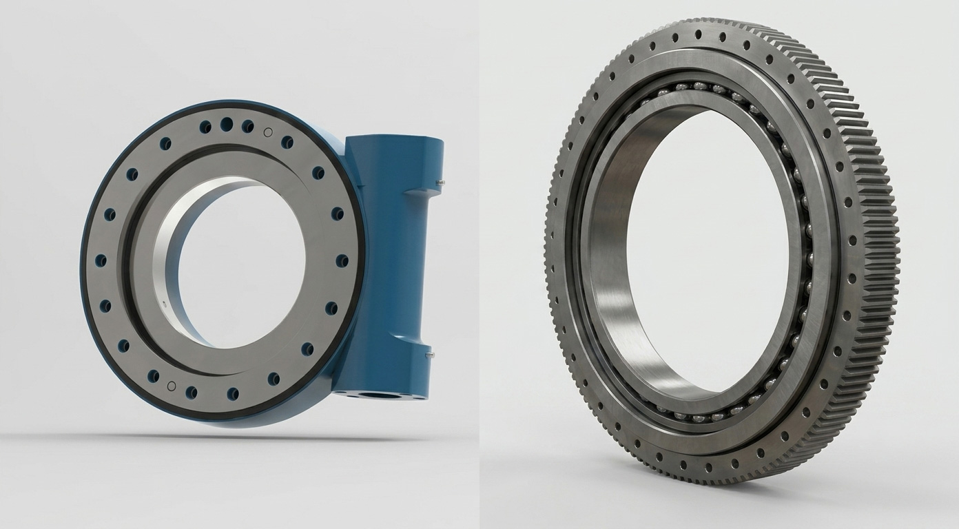
What is a slew drive? A slew drive is a compact rotary transmission unit that combines a slewing bearing, gear system, housing, and mounting interface to turn a load around a fixed axis. It is often selected when equipment needs controlled rotation while carrying axial load, radial load, overturning moment, or a combination of all three.
The main question behind slew drive applications is not simply whether a drive can rotate a machine. The real question is whether it can keep the required position, survive the load direction, resist the environment, and maintain safe operation through the actual duty cycle. A drive that performs well on a solar tracker may be the wrong choice for a forestry grapple, a crane, or a high-frequency automated turntable.
Luoyang Slewring Bearing Co., Ltd. supplies Slew Drive, Slewing Bearing, and Customized Slew Drive solutions for equipment builders that need to match rotational architecture to working conditions. Our engineering team can provide a technical proposal within 24 hours, which helps project teams identify missing load, mounting, and control data before committing to a configuration.
Start with the load path rather than the industry name
Industry labels are useful, but they do not define the drive requirement by themselves. Two crane systems may both use a rotary drive, yet one may make slow, controlled deck-crane movements while the other experiences repeated side loading, shock, and frequent starts. The load path and duty cycle determine whether their drive architecture can be shared.
A buyer should first separate the forces acting on the rotating structure. This prevents a common error: choosing based on output torque alone. Output torque is only one part of the selection. The bearing and mounting arrangement must also support the loads created by the attachment, center of gravity, acceleration, wind, and external impacts.
Axial load, radial load, and overturning moment affect different parts of the system
- Axial load acts along the rotation axis. A horizontal platform carrying vertical weight often creates a strong axial component.
- Radial load acts perpendicular to the rotation axis. Side forces from a boom, grapple, or off-center attachment can increase radial loading.
- Overturning moment occurs when the load center sits away from the rotation center. A long boom, solar panel row, or large antenna can create this condition even when its total mass appears moderate.
- Dynamic shock comes from impact, sudden braking, digging, swinging, or material handling. It can be more demanding than steady rotation because load direction changes quickly.
Conclusion: select the bearing capacity and housing arrangement from the combined load case, not from the equipment category alone. This approach fits cranes, excavators, forestry attachments, and mobile machinery where the attachment is offset from the rotation center. It does not replace a full engineering review when the machine has strong impact loads, unusual mounting stiffness, or multiple operating positions.
For applications where the bearing itself is the dominant design item, review the available Slewing Bearing configurations before treating the drive as a separate component. The gear train turns the load, but the bearing arrangement carries the structural demand.
Industry-by-industry constraint matrix for drive feasibility
The following comparison shows why a similar-looking drive can suit one sector and fail in another. The matrix focuses on the conditions that usually change the selection: load direction, backlash tolerance, environment, rotation frequency, and the consequence of an unexpected loss of position or drive function.
| Industry or equipment | Load direction | Backlash tolerance | Environment | Rotation frequency | Failure consequence | Selection focus |
|---|---|---|---|---|---|---|
| Single-axis solar tracker | Mostly predictable gravitational and wind-driven loads | Position repeatability matters because tracking error affects panel alignment | Outdoor heat, dust, moisture, and corrosion exposure | Slow and periodic movement | Energy loss across a tracker row and maintenance access costs | Environmental sealing, repeatable positioning, and mounting alignment |
| Port or shipboard crane | Combined radial load and overturning moment from a boom and lifted load | Controlled motion is needed, but structural load support is usually the first concern | Moisture, salt exposure, and corrosion risk | Intermittent, with variable operating periods | Safety risk, lost handling capacity, and equipment downtime | Load-case review, corrosion protection, sealing, and safe holding behavior |
| Mining excavator or heavy equipment | High combined loads, vibration, and changing shock directions | Lower priority than load survival in many tasks, but excessive clearance can affect machine control | Dust, debris, vibration, temperature changes, and impact exposure | Repeated work cycles | Production stoppage, repair cost, and machine safety concerns | Heavy-duty bearing support, housing strength, and resistance to cyclic loading |
| Forestry grapple | Frequent side loading and abrupt direction changes from gripping and handling logs | Controlled attachment response can matter during positioning | Dirt, moisture, debris, and impact exposure | Frequent reversing motion | Attachment control loss, reduced productivity, and field-service burden | Resistance to reversal, side load, contamination, and cyclic duty |
| Automated turntable | Often more predictable, but off-center fixtures create moment load | Often tight because position affects assembly, inspection, or transfer accuracy | Usually cleaner indoor conditions, though process contamination may remain | Can be frequent or continuous | Part misalignment, rejected output, or line stoppage | Backlash control, repeatability, acceleration profile, and cycle-life review |
| Truck-mounted crane | Strong moment load from an extending boom and varying outreach | Moderate to tight depending on operator control requirements | Outdoor contamination, rain, road debris, and varying temperatures | Intermittent duty | Load-handling safety risk and lost vehicle availability | Mounting rigidity, boom-load case, sealing, and controlled rotation |
Conclusion: a low-speed outdoor solar system and a high-cycle indoor turntable may both rotate through limited angles, but their limits are different. Solar equipment places more emphasis on exposure and repeatable tracking. Automation places more emphasis on backlash, acceleration, and repeated positioning. This matrix is an early screening tool, not a substitute for calculated load data or a review of the supporting structure.
For example, Luoyang Slewring Bearing Co., Ltd. supplied SP-I 0229 spur gear slew drives for single-axis solar tracker projects in Brazil, Argentina, and Chile. Those projects reported energy yield increases of up to 40%, but that result belongs to the stated solar-project context and should not be treated as a general result for every installation. Desert and outdoor tracker projects also need to define sealing, wind loading, mounting alignment, and control strategy before selecting a unit.
How backlash, gear architecture, and duty cycle interact
Backlash is the free movement that can occur when the gear direction reverses before full tooth contact transfers to the opposite flank. Some backlash is normal in geared systems. The engineering question is whether the resulting lost motion changes the machine’s ability to track, place, aim, or hold its intended position.
Conclusion: prioritize backlash control when angular position directly affects output quality, alignment, or safety. This fits automated turntables, antenna systems, and some solar tracking equipment. It may not be the first selection factor for an excavator attachment, where shock load, bearing capacity, and contamination resistance may dominate. Still, backlash should not be ignored if the attachment must stop accurately near people, structures, or a precise work zone.
Choose the architecture from the operating condition
| Drive approach | Best fit | Why it may fit | When it may not fit |
|---|---|---|---|
| Single worm drive | Many controlled, low-speed rotary systems | Provides a compact transmission approach for applications that need controlled rotation and, where designed for it, self-locking behavior | May require further review where extreme moment load, high reversal demand, or very tight positioning requirements are present |
| Double worm drive | Applications needing improved rotational support and controlled motion under demanding load conditions | Uses two worm engagement points to support demanding rotational work | Not automatically necessary for light, predictable, low-duty installations |
| Spur gear drive | Solar tracking and applications where gear-drive layout suits the equipment structure | Can support a direct arrangement for periodic rotational movement | Must still be evaluated for exposure, loading, mounting stiffness, and required positioning behavior |
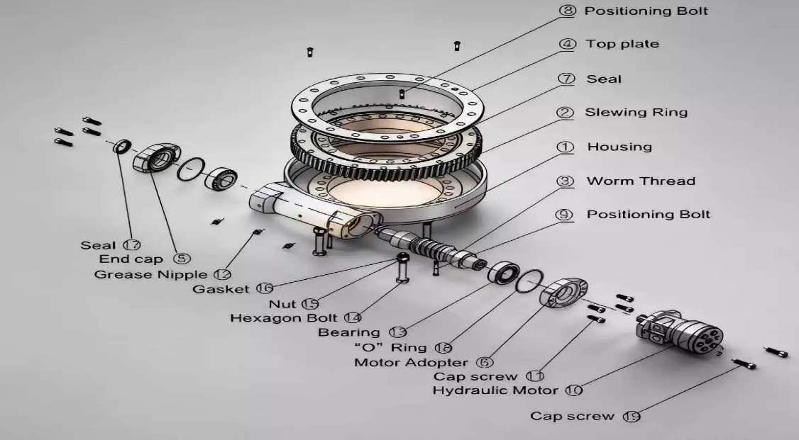
A Worm Gear Slew Drive is commonly considered where controlled, low-speed rotation and holding behavior are important. However, self-locking should never be assumed from the product category alone. Confirm the load direction, vibration, external force, lubrication condition, and safety requirement with the supplier for the exact configuration.
Double worm designs are useful when the application requires more support under demanding cyclic loads or when rotation quality is affected by load distribution. In a real project example, a forestry equipment manufacturer in British Columbia used WED14-86-25BHR.5 double worm slew drives for grapple machines, with stated precision of no more than 0.13°. This is relevant to forestry equipment with frequent attachment movement, but it does not prove that the same configuration is suitable for every grapple geometry or hydraulic control system.
Rotation frequency changes the result. A drive that moves a solar tracker periodically has a different wear pattern from an automation table that reverses repeatedly during each production cycle. Buyers should provide the motion profile: rotation angle, direction changes, stop time, acceleration, and expected operating schedule. Without that data, comparing two drives by maximum torque alone can lead to a poor match.
Request Your Custom Slew Drive or Bearing Spec
Tell us your load, speed, and environment — receive a tailored 100–5000 mm slewing drive or slewing bearing proposal with 3D drawings within 24 hours.
Environmental exposure can change a workable design into a service problem
Outdoor equipment is not defined only by rain. Dust, salt, chemical contact, ultraviolet exposure, standing water, temperature changes, and abrasive debris can all affect the selection. The housing, sealing approach, corrosion protection, lubricant plan, and maintenance access must match the actual site rather than a general “outdoor” label.
Conclusion: specify the environmental condition in measurable project terms before comparing suppliers. This fits marine cranes, ports, mining equipment, desert solar sites, and forestry machinery. It does not mean every outdoor project requires the highest available protection level; unnecessary protection can add cost or constrain design choices without improving the real application.
- Marine and port equipment: assess salt exposure, washdown practices, corrosion risk, and downtime consequences. A sealed housing may reduce contamination entry, but external fasteners, mating structures, and maintenance routines also matter.
- Mining and forestry equipment: assess debris packing, mud, vibration, impact, and field-service access. Protection against contamination is useful, but poor mounting rigidity or overload can still damage the system.
- Solar sites: assess dust, heat, rainfall, wind load, and long rows of repeated equipment. A single installation issue can become a fleet-level maintenance issue when it is repeated across a field.
- Indoor automation: assess process dust, cleaning agents, cable routing, and fixture interference. A clean building does not guarantee a clean drive environment.
Luoyang Slewring Bearing Co., Ltd. offers slew drives with protection up to IP66 and anti-corrosion rating up to C4H, depending on the selected design and working condition. Material selection can include ductile cast iron, alloy steel, stainless steel, or forged alloy steel based on load, speed, and environmental exposure. These options should be matched to the project requirement rather than treated as automatic upgrades.
A marine crane illustrates this point. The company supplied 20 WEA17-104-25H-R-REV.D units to UK Ocean Marine Systems for shipboard crane systems, and another marine equipment manufacturer in Newcastle used WEA9-61-25HR worm gear slew drives for ship deck cranes. These cases show that marine equipment can require dedicated attention to exposure and load conditions. They do not establish one universal marine specification.
Prevent selection errors with a project data checklist
Most early selection errors come from missing information, not from choosing the wrong catalog series. A supplier cannot reliably assess a drive when the request only says “for a crane,” “for a tracker,” or “for a rotating platform.” The machine’s actual loads, mounting arrangement, and motion profile need to be stated.
Conclusion: use a structured request package before asking for a final recommendation. This fits OEMs, system integrators, and equipment retrofit teams that need a technically defensible comparison. It may be less detailed for a like-for-like replacement when the original part data, drawings, and service history are already available.
- Define the rotating load. State the mass, center-of-gravity location, and all attachment positions that change the moment load.
- Describe force direction. Identify axial load, radial load, overturning moment, shock, wind force, and any external side force.
- Map the duty cycle. Provide rotation angle, speed range, starts and stops, reversing motion, expected daily use, and idle time.
- Set position requirements. Define whether the drive only rotates, stops at indexed positions, tracks an angle, or must hold against external force.
- Describe the environment. Include indoor or outdoor use, dust, moisture, salt exposure, temperature changes, washdown, and corrosion concerns.
- Check the mounting structure. Provide interface dimensions, available envelope, bolt pattern, support stiffness, and whether the mounting faces are machined and aligned.
- Identify safety consequences. Explain what happens if motion drifts, stops unexpectedly, or loses position. This helps determine whether additional mechanical or control safeguards are needed.
- Request verification evidence. Ask how the supplier confirms dimensions, load-related assumptions, material choice, and inspection method for the selected unit.
Do not confuse a high nominal torque figure with a complete application answer. A drive can have enough turning force yet still face unsuitable bearing loading, excessive structural deflection, poor sealing for the site, or inadequate position control. Likewise, specifying the highest precision grade without understanding the mounting and control system may add expense without improving machine performance.
Luoyang Slewring Bearing Co., Ltd. operates an ISO 9001:2015-certified facility with CNC machining centers and CMM three-coordinate inspection. Our stated quality process includes CMM inspection and dynamic load testing for slewing bearings. For projects that need nonstandard interfaces or operating conditions, a Customized Slew Drive can be evaluated from the machine’s actual loads and installation limits rather than forcing a standard product into an unsuitable arrangement.
Use verified cases to set realistic application boundaries
Real application examples are useful when they are treated as references, not as shortcuts around engineering data. The best use of a case is to identify which conditions are comparable: equipment type, load direction, environment, accuracy need, and duty pattern. If those conditions differ, the case should prompt questions rather than become a direct specification.
For port crane systems, a South Korean equipment manufacturer placed a repeat order for 20 WEA9-62-25HR single worm slew drives. The stated application requirements included no more than 0.15° tracking precision, IP65 sealing, and self-locking behavior. This provides a practical reference for port equipment with controlled positioning needs, but a different boom length, lifting load, or corrosion exposure can change the correct selection.
For heavy-duty wheel steering systems, a Houston engineering machinery manufacturer used 150 WED17-104-25HR double worm slew drives. The case supports the use of double worm arrangements in a demanding steering application. It does not mean every steering system needs a double worm drive, because vehicle weight, axle layout, tire force, steering angle, and duty conditions can vary widely.
For indoor automation, a Manchester manufacturer used 100 SP-I 0841-32.1 units for automated turntable systems. That case helps show why controlled motion and repeatable rotation can matter in production equipment. A buyer should still verify fixture weight, offset load, acceleration, control feedback, and required stop position before applying the same approach.
Standard products are available from a minimum order quantity of one set, while customized products start from five sets. Sample orders are welcome for testing and evaluation. Standard production is stated as a nine-day cycle, while rapid prototyping is stated at three days; final timing should still be confirmed against the selected model, customization level, and current production schedule.
A technically sound selection starts with the condition that most limits the machine: structural loading, position control, environmental exposure, cycle frequency, or safety consequence. Once that limit is clear, the product type, gear arrangement, inspection requirement, and mounting design become much easier to evaluate.
Request Your Custom Slew Drive or Bearing Spec
Tell us your load, speed, and environment — receive a tailored 100–5000 mm slewing drive or slewing bearing proposal with 3D drawings within 24 hours.
 WhatsApp

 +8613903880726