



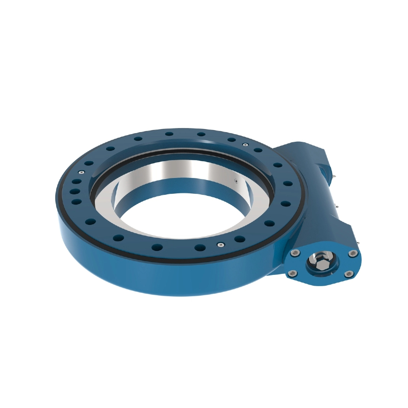
What is a slew drive? It is a rotary transmission unit that combines a slewing bearing, gearing, housing, and a drive input to rotate a machine component under load. Engineers use it where controlled rotation must fit within a limited machine envelope.
The challenge is not simply choosing the smallest unit. The right slew drive features must fit the available radial space, vertical clearance, mounting pattern, motor envelope, service access, and duty requirements at the same time. A drive that fits in CAD but blocks a motor, grease point, cover, or cable route can still delay the machine build.
This guide gives OEM engineers and project designers a layout-first selection process. The goal is to produce a release-ready installation package before requesting a final quotation or starting prototype production.
Lewis, Senior Mechanical Design Engineer has spent more than 30 years working on heavy equipment and power transmission design, including slewing bearings, slew drives, worm gear reducers, tolerance verification, and material selection for more than 200 equipment projects.
Start with a controlled installation envelope instead of a catalog size
Begin by defining the space the rotary unit may occupy, not by selecting a familiar model. Create a protected volume around the rotation center that includes the supporting structure, rotating structure, motor, cable bend area, covers, fasteners, and maintenance access.
The conclusion is simple: use the worst-case installed envelope as the selection boundary. This approach fits concept design, redesigns of existing machines, and retrofit projects where surrounding components are already fixed. It does not replace load and torque calculations; it prevents a technically adequate drive from becoming physically unusable.
Collect these inputs before comparing drive types
- Rotation center: Mark the required centerline and identify whether it is fixed by the upper structure, turntable, mast, or tooling plate.
- Static interference zones: Model frame rails, columns, covers, hydraulic manifolds, battery boxes, sensors, and guarding that cannot move.
- Moving interference zones: Include booms, linkages, payloads, hoses, cable carriers, and other parts that enter the rotary sweep area.
- Mounting surfaces: Record available face orientation, mounting thickness, hole access direction, and whether bolts can be installed from one side only.
- Drive input space: Reserve room for the motor, brake if used, connector, cable exit, and tool access for installation.
- Operating conditions: Provide load direction, rotation speed, duty pattern, shock exposure, ambient environment, and required positioning behavior.
Do not use only a top-view sketch. A top view may show acceptable radial clearance while hiding a vertical collision between a motor and a guard. Use at least plan, elevation, and section views around the drive centerline.
At Luoyang Slewring Bearing Co., Ltd., the engineering team can prepare a technical proposal within 24 hours when the main layout and operating inputs are available. Missing load data can sometimes be refined later, but an unknown mounting orientation or unavailable motor space often blocks practical selection immediately.
Prioritize geometry, housing, mounting, and motor orientation in the right order
When space is limited, rank the features that create hard interference before reviewing secondary preferences. Low-profile geometry, housing style, mounting interfaces, and motor orientation should be evaluated in that order because each one changes the usable machine envelope.
| Layout priority | What to check | Why it prevents conflicts | Best-fit situation | Limit or failure reason |
|---|---|---|---|---|
| Low-profile geometry | Overall vertical stack from the base structure to the rotating plate | Reduces the chance that the drive projects into a cover, platform, boom path, or low overhead area | Turntables, compact automation cells, solar tracker structures, and equipment with restricted height | A lower profile alone does not confirm adequate load capacity, bolt access, or motor clearance |
| Housing style | Housing edges, gear protection, sealing needs, and support contact surfaces | Determines where the drive can sit against a frame and where surrounding parts must remain clear | Machines with side rails, protective guards, or exposed outdoor installation | A housing that fits the frame may still conflict with service tools or cable routing |
| Mounting interface | Bolt-circle access, plate thickness, flatness, interface direction, and installation sequence | Prevents a design where bolt heads, washers, or tightening tools cannot be used after assembly | Closed-box frames, one-sided access structures, and replacement installations | Do not alter mounting holes without engineering review because interface changes affect load transfer |
| Motor orientation | Motor body, connector, brake, gearbox, and cable exit direction | Prevents the most frequent late-stage collision: a selected drive fits, but the attached motor does not | Compact enclosures, mast systems, mobile machinery, and automation stations | Changing orientation may affect access, wiring, environmental protection, or drive arrangement |
Use low-profile geometry first when vertical height is the fixed constraint. For example, a turntable located under a machine deck may have enough diameter for a larger unit but very little space between the base frame and the rotating platform. In that situation, height is the first screening factor, while a larger radial envelope may still be acceptable.
Select housing style next because the housing establishes the real boundary, not just the bearing centerline. A protective housing can support use in demanding environments, and Luoyang Slewring Bearing Co., Ltd. offers protection up to IP66 and anti-corrosion capability up to C4H for suitable applications. Those ratings should be selected for the actual exposure condition, not added when the equipment operates indoors in a protected enclosure.
Then validate the mounting interface with the manufacturing team. Confirm that the supporting plate is accessible for drilling, bolt insertion, tightening, and later inspection. If the structure is a welded box section with only one accessible face, a standard interface may be unsuitable even when its outside dimensions appear correct.
Finally, place the motor model in the CAD assembly rather than showing only a shaft or simplified block. Include connector height and cable bend space. This applies especially to a Worm Gear Slew Drive, where the input-side arrangement can determine whether the complete assembly fits a narrow machine bay.
Use a step-by-step layout validation sequence before releasing the design
Run the same sequence for a new machine, a replacement unit, or a customized design. The sequence prevents teams from approving a drive based only on a product outline and discovering interference after steelwork or guards are released.
- Lock the rotation center. Place the rotary centerline from the function of the machine, such as the center of a platform, mast, tool, or payload. Successful progress means the centerline is referenced to fixed structural datums, not estimated from a visual model.
- Build the non-negotiable keep-out zones. Add parts that cannot be moved, including frames, cylinders, electrical cabinets, safety guards, and fixed covers. The common mistake is omitting fasteners and service covers because they are not part of normal operation.
- Model the rotating envelope. Sweep the upper structure and its payload through the intended rotation range. Check both normal operation and positions where hoses, cable carriers, or attachments take their largest path.
- Place the drive outline and housing. Use the supplier drawing rather than a generic circular symbol. Confirm the base support and rotating interface sit on the intended faces without forcing the unit into an unsupported overhang.
- Add the motor and electrical envelope. Place the motor, connector, brake, and cable exit in the actual orientation. A successful check shows that installation, wiring, and removal remain possible without removing unrelated machine assemblies.
- Check mounting tool access. Insert representative tool paths for each mounting fastener. If a wrench or socket cannot reach a bolt after neighboring parts are installed, change the interface or assembly order before releasing drawings.
- Review load and environmental requirements. Send the final layout, load data, duty, speed, and environment to the drive supplier for selection review. Geometry confirms fit; it does not independently verify capacity or service life.
For standard products, Luoyang Slewring Bearing Co., Ltd. accepts an MOQ of one set, which can help an OEM validate the physical installation before broader procurement. Sample orders are also available for testing and evaluation. This is useful when the machine envelope is proven in CAD but the team still needs to confirm assembly access on a physical frame.
A customized interface should be considered when the basic drive type is right but the housing, mounting direction, or motor arrangement creates a fixed conflict. A Customized Slew Drive is most appropriate after the team has identified the specific interference and confirmed that the surrounding machine geometry cannot be changed. It is not the first answer when a standard housing can be installed by changing a removable cover or assembly sequence.
Request Your Custom Slew Drive or Bearing Spec
Tell us your load, speed, and environment — receive a tailored 100–5000 mm slewing drive or slewing bearing proposal with 3D drawings within 24 hours.
Choose the transmission arrangement based on layout and positioning needs
The transmission type should support the installation concept, not be selected from naming alone. Worm, double worm, and spur arrangements create different packaging and control considerations, so compare them against the machine’s real operating needs.
| Drive arrangement | Layout decision point | Useful application fit | When it may not fit |
|---|---|---|---|
| Single worm arrangement | Check available input-side space and whether the motor can sit beside the rotary axis | Applications requiring a compact integrated rotary transmission, including crane-related equipment | May be unsuitable when the required duty or control requirement calls for a different arrangement |
| Double worm arrangement | Reserve space for the additional drive-side configuration and verify the support structure | Heavy-duty applications where the operating requirement supports a double worm solution | Do not choose it only for perceived strength if the added package creates a motor or frame conflict |
| Spur gear arrangement | Review how the drive and motor package align with the rotating structure and protective covers | Solar tracker and automated turntable applications where the installation arrangement suits the design | Not automatically the best choice for applications that require the operating characteristics of a worm arrangement |
Use a single worm arrangement when its input location fits the machine envelope and the application requirements support it. Luoyang Slewring Bearing Co., Ltd. supplied WEA9-62-25HR single worm slew drives for a South Korean port equipment manufacturer’s crane systems, where the listed requirements included IP65 sealing, self-locking behavior, and tracking precision of no more than 0.15 degrees. That result is specific to that project and should not be treated as a universal specification for every crane system.
Choose a Double Worm Slew Drive when the application review supports it and the machine has room for its complete configuration. One relevant case involved HWE21-94-25HR.1 double worm slew drives for an Australian heavy equipment manufacturer’s mining excavators. The example shows the arrangement can serve demanding equipment, but final suitability still depends on the actual load case, duty cycle, mounting structure, and available envelope.
Consider a Spur Gear Slew Drive when its package and control needs align with the design. SP-I 0229 spur gear drives were used in solar projects in Brazil, Argentina, and Chile for single-axis trackers, with reported energy yield improvement up to 40 percent. Energy yield depends on the full tracker system and site conditions, so that project outcome should not be used as a general yield promise.
Catch the layout mistakes that cause late redesigns
Most installation problems are visible early if the CAD model includes the complete assembly rather than only the rotary ring. Use the following list during design reviews with mechanical, electrical, manufacturing, and service teams.
- Mistake: checking only the bearing diameter. The observable effect is a drive that fits around the rotation center but projects into a side guard or frame rail. Recover by modeling the full housing and all external attachments.
- Mistake: ignoring motor removal space. The motor may operate correctly but cannot be replaced without removing a major welded or guarded assembly. Recover by creating a removal path and confirming access before finalizing covers.
- Mistake: placing bolts where tools cannot reach. The assembly team finds that a fastener is hidden behind a motor, plate, or cross member. Recover by changing the assembly sequence, revising access openings, or reviewing a different interface.
- Mistake: treating seals as separate from layout. The drive may fit initially, but an unprotected arrangement can be unsuitable for dust, water, or corrosion exposure. Recover by defining the operating environment before selecting protection requirements.
- Mistake: changing the drive orientation after selection. A late orientation change can create cable conflicts, inaccessible connectors, or unexpected housing interference. Recover by reviewing the full motor and wiring envelope with the supplier drawing.
- Mistake: selecting a standard unit before sharing the machine section view. A catalog model may meet functional needs yet require costly structural changes. Recover by sending plan, elevation, section, and mounting details with the initial request.
Quality verification also matters once the package is correct. Luoyang Slewring Bearing Co., Ltd. operates an ISO 9001:2015 certified quality management system, and every slewing bearing passes CMM three-coordinate inspection and dynamic load testing according to the company’s stated quality control practice. For projects that require supplier review, factory audit reports are available on request.
Material selection should follow the working condition rather than a default preference. The company uses ductile cast iron, alloy steel, stainless steel, and forged alloy steel according to load, speed, and environment. A compact layout cannot compensate for material that is poorly matched to corrosion exposure, cyclic loading, or the supported structure.
Finish with a release checklist that separates fit from approval
A model is ready for engineering release only when the team can verify both physical fit and the information needed for final selection. Use this checklist to distinguish a preliminary concept from an installation package that a supplier can review.
- The rotation center is tied to fixed machine datums.
- The drive housing, not only the bearing centerline, is modeled.
- The selected motor, connector, brake, and cable exit are included.
- Static machine parts and moving components have been checked through the operating range.
- Mounting bolts, washers, tightening tools, and assembly order have been reviewed.
- Service access for inspection, wiring, lubrication where applicable, and motor replacement is available.
- Load direction, duty, speed, environment, and required positioning behavior are documented for supplier review.
- The support structure and mounting interface are shared with the proposed drive drawing.
If all checklist items are complete, the project is ready for a technical proposal or prototype decision. If only the outside envelope is confirmed, return to the motor and mounting-interface checks before committing to the model.
Luoyang Slewring Bearing Co., Ltd. has six production lines, an 8,000 square meter manufacturing facility, CNC machining centers, and annual capacity of 100,000 sets. Standard production is listed at a 9-day cycle, while rapid prototyping can be completed in 3 days when the project requirements support that route. The company also provides a 2-year extended quality warranty, 48-hour technical response, and free replacement for confirmed manufacturing defects.
For a constrained machine envelope, the best result is not the smallest drive on paper. It is the unit whose housing, mounting pattern, motor orientation, service access, and operating requirements all work together in the released machine design.
Request Your Custom Slew Drive or Bearing Spec
Tell us your load, speed, and environment — receive a tailored 100–5000 mm slewing drive or slewing bearing proposal with 3D drawings within 24 hours.
 WhatsApp

 +8613903880726