



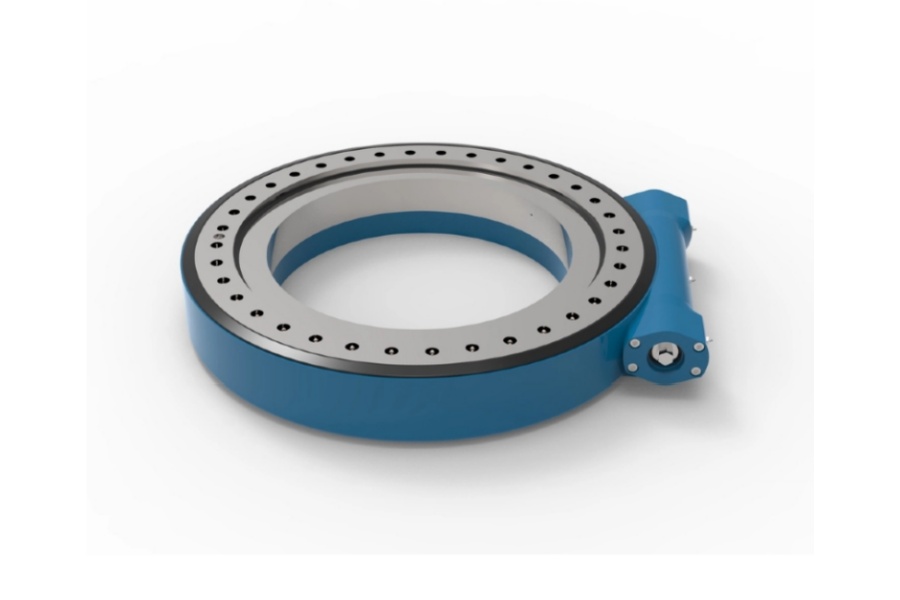
What is a slew drive? A slew drive is a compact rotary assembly that combines a slewing bearing, a gear transmission, and a housing into one unit. It is commonly used where a machine must rotate a load slowly, carry radial and axial forces, resist overturning moment, and hold a selected position.
The real question is not whether a slew drive can turn a load. Standard gearboxes can also provide rotary motion. The engineering question is where slew drive applications offer a better system-level answer than a motor, gearbox, external pinion, separate bearing, and brake arrangement.
For early concept selection, the difference often comes down to three requirements: holding torque, compact mounting, and controlled low-speed positioning. If all three are present, a slew drive deserves serious consideration. If high continuous speed, long travel rotation, or frequent high-speed reversals dominate, a conventional gearbox arrangement may be the better fit.

Define the rotary-motion problem before comparing product types
A standard gearbox mainly reduces speed and multiplies torque between a motor and an output shaft. It does not automatically provide a large-diameter bearing, a mounting interface for a rotating platform, or a built-in way to resist moment loading. Those functions must usually be designed around the gearbox.
A slew drive packages those functions together. The rotating output is supported by an integrated slewing bearing, while a worm or spur gear arrangement transmits motor torque to the bearing gear. This layout can reduce the number of separate mechanical interfaces in equipment such as tracked solar systems, crane booms, turntables, forestry grapples, and aerial work platforms.
The conclusion is straightforward: choose a slew drive when the rotating member is itself a loaded structure. A standard gearbox is often more suitable when the output only drives a shaft, drum, conveyor, pump, or wheel and another part of the machine already carries the load.
| Design question | Slew drive tends to fit when | Standard gearbox tends to fit when | Limit to check |
|---|---|---|---|
| What supports the rotating load? | The drive must support radial, axial, and moment loads through one mounted assembly. | A separate shaft bearing arrangement already supports the load. | Do not assume the drive can carry every load case without bearing calculations. |
| How is position held? | The equipment needs resistance to back-driving at low speed or a compact holding solution. | A brake, locking pin, or servo control system is already included. | Self-locking behavior depends on the worm design, load direction, lubrication, and operating conditions. |
| How fast does the output rotate? | Rotation is slow and indexed, tracked, or limited in angular travel. | The output runs continuously at moderate or high speed. | Thermal conditions and duty cycle can rule out a compact drive. |
| How much installation space is available? | Envelope height and part count must be reduced. | There is room for a gearbox, coupling, brake, and separate bearing. | Compact mounting does not remove the need for a stiff machine frame. |
For example, a solar tracker rotates slowly through the day and must maintain panel orientation under changing loads. A compact drive mounted between the tracker structure and the rotating torque tube can be easier to package than a separate reducer and bearing system. By contrast, a continuous conveyor shaft normally needs speed reduction, not a large rotating support bearing.
Luoyang Slewring Bearing Co., Ltd. manufactures both slew drives and slewing bearing products, so the architecture can be evaluated as a complete rotary support problem rather than only as a gear reduction problem. Where the load support should remain separate, a Slewing Bearing with an independent drive train may offer more design flexibility.
Use an operating-envelope map to decide when a slew drive is justified
The most useful boundary is an operating envelope, not a broad list of industries. High holding torque, compact mounting, and slow-speed positioning are the conditions that most often justify a slew drive over conventional gearboxes. One condition alone is not enough; the decision becomes stronger as two or three conditions occur together.
| Operating condition | Why a slew drive can be favored | Typical equipment fit | When the answer changes |
|---|---|---|---|
| High holding demand at low output speed | A worm-driven arrangement can resist back-driving and can support controlled positioning. | Solar trackers, boom rotation, small crane turntables, antenna positioning. | Use a gearbox with a rated brake when holding security must be independently verified. |
| Large offset load or overturning moment | The integrated bearing supports a rotating platform while transmitting torque. | Manlifts, forestry attachments, truck-mounted equipment. | Use a separate heavy bearing and drive when load magnitude or structure size exceeds the available drive envelope. |
| Limited mounting space | The bearing and reduction stage share one housing and mounting pattern. | Compact automation cells, mobile equipment, solar tracker rows. | Use separate components if service access or frame geometry requires distributed mounting. |
| Slow, repeatable angular movement | Low-speed positioning aligns with the duty pattern of many worm and spur slew drives. | Indexing tables, scanner platforms, tracking systems. | Use servo gearbox systems for frequent rapid indexing or high dynamic response. |
| Outdoor contamination risk | A sealed housing can reduce exposure of the transmission components. | Construction, marine equipment, agricultural machinery. | Confirm sealing, corrosion protection, grease compatibility, and temperature range for the actual site. |
This map reflects mechanical function, not a claim that one product type is always superior. A slew drive does not replace a gearbox simply because the machine rotates. It is favored when the drive must also act as a rotary support module.
Consider a compact aerial work platform. The upper structure may rotate slowly, carry an offset boom load, and need stable parked positioning. A properly selected Aerial Work Vehicle Slew Drive can reduce the need to engineer a separate bearing and gear train. It is not the automatic choice if the design requires fast, continuous rotation with aggressive acceleration and deceleration.
The interpretation should remain measured. High holding torque can also be achieved with a conventional gearbox plus a brake. Compactness can also be achieved with a custom transmission housing. The reason to select a slew drive is that it may combine these functions with a load-carrying rotary bearing in a single mounting unit.
Request Your Custom Slew Drive or Bearing Spec
Tell us your load, speed, and environment — receive a tailored 100–5000 mm slewing drive or slewing bearing proposal with 3D drawings within 24 hours.
Compare the two architectures at the system level, not only by ratio
Comparing gear ratio alone can lead to a poor selection. The lower-priced reducer may require a bearing, pinion, brake, couplings, shaft supports, guards, and added machining before it becomes a working rotary system. The correct comparison includes all components needed to rotate, support, hold, and service the load.
| System element | Slew drive architecture | Standard gearbox architecture | Buyer implication |
|---|---|---|---|
| Speed reduction | Integrated worm or spur transmission. | Separate reducer connected to an output shaft or pinion. | Compare torque, ratio, duty cycle, and motor interface. |
| Rotary load support | Integrated slewing bearing. | Separate bearing or turntable bearing assembly. | Calculate axial load, radial load, and overturning moment. |
| Holding function | May benefit from worm-drive resistance to back-driving. | Usually supplied by a brake, lock, or control system. | Verify holding performance under the worst load direction. |
| Installation work | One assembled unit mounted to the machine structure. | Multiple aligned parts and interfaces. | Assess machining, assembly time, alignment risk, and field replacement method. |
| Service access | Fewer exposed drive parts. | Individual components can be replaced separately. | Integrated packaging may simplify installation but can change repair strategy. |
| High-speed suitability | Usually selected for low-speed rotary duties. | Often more adaptable for continuous higher-speed shaft drives. | Do not force a slew drive into a high-speed duty without thermal and life validation. |
The best cost comparison is therefore a system cost review, not a unit-price review. Ask the design team to list the bearing, brake, gear, housing, shafts, couplings, mounting plates, seals, machining, and assembly labor required for each option. A slew drive can reduce the bill of materials in one machine, while a separate gearbox system may remain preferable where existing shafts and bearing arrangements are already standardized.
For heavy rotating structures, bearing selection remains a separate engineering task even when the transmission layout is clear. A Heavy load slewing bearing may be the better route when the machine needs a large support bearing and the drive must be independently sized for unusual torque, speed, or redundancy requirements.
Follow a five-step concept selection procedure
Use the following procedure before asking suppliers for a model number. It separates the machine requirements from the supplier’s catalog range and reduces the chance of choosing by outside diameter alone.
- Define the moving structure. Record the rotating mass, center of gravity, attachment geometry, range of rotation, and all operating positions. The load center matters because offset distance creates overturning moment.
- Map all load cases. Include axial force, radial force, overturning moment, wind exposure where applicable, shock events, transport loads, and parked loads. Select from the worst credible combination, not only the normal running condition.
- Set motion requirements. Identify output speed, acceleration, frequency of starts and stops, required positioning accuracy, and whether rotation is continuous or limited. A low-speed tracker and a rapidly indexing machine may both rotate, but their transmission needs are different.
- Decide how the load will be held. State whether the mechanism needs self-locking behavior, an external brake, a mechanical lock, or closed-loop motor control. Do not treat a general worm-drive description as a substitute for a holding-load verification.
- Check the installation interfaces. Confirm mounting faces, bolt pattern, frame stiffness, motor connection, access for lubrication or inspection, and environmental sealing. A compact drive cannot compensate for a flexible mounting structure.
The clear recommendation is to submit this data as a load-and-duty sheet with the request for quotation. It fits any early-stage project where several architectures remain open. It is less useful only when a replacement part must match an existing approved design, in which case the existing interface and part specification become the starting point.
Luoyang Slewring Bearing Co., Ltd. provides technical proposals within 24 hours for supplied requirements and supports standard product orders from one set. For projects that need a different mounting pattern, output interface, or working condition, a Customized Slew Drive may be considered; customized products have a stated minimum order quantity of five sets.
Match the drive layout to the duty instead of relying on industry labels
Industry names are useful starting points, but they do not determine the correct rotary architecture. Two mining machines can have very different needs: one may need a compact, high-holding-torque rotation unit, while another may need a separate gearbox system built around an established heavy bearing structure.
Single worm arrangements suit many low-speed holding duties
A worm gear slew drive is often considered where one motor drives slow rotation and the load should resist back-driving. This can fit crane, platform, and tracker duties when the load case, gear contact, mounting stiffness, and holding requirement have been checked.
A real application example is a South Korean port equipment manufacturer that placed a repeat order for 20 WEA9-62-25HR single worm slew drives for port crane systems. The specified case included tracking precision of no more than 0.15 degrees, IP65 sealing, and self-locking. That result describes that customer’s stated application; it should not be treated as a universal specification for every port crane.
Double worm arrangements can address demanding directional loads
A double worm arrangement may be useful where the machine needs greater torque distribution and stability than a single-worm concept can provide. It is often considered for heavy equipment, steering mechanisms, and asymmetric working loads, but the final choice still depends on the full bearing and duty-cycle calculation.
For example, an Australian heavy equipment manufacturer used HWE21-94-25HR.1 double worm slew drives for mining excavators. Another documented case involved 30 WED14-86-25BHR.5 units for forestry grapple machines in British Columbia, Canada, with stated precision of no more than 0.13 degrees. These cases show where a Double Worm Slew Drive has been applied, not a substitute for load verification on another machine.
Spur gear arrangements can fit tracker and turntable layouts
Spur gear slew drives can be relevant when the system needs controlled rotation but the preferred gear layout differs from a worm-drive arrangement. They should be evaluated for torque, environmental exposure, control strategy, and whether external braking is required.
Documented solar projects in Brazil, Argentina, and Chile used SP-I 0229 spur gear slew drives in single-axis tracker systems, with reported energy yield improvement up to 40 percent. That figure belongs to those project cases and may also reflect tracker design, controls, site conditions, and baseline equipment. It is not a general energy-yield promise for every solar installation.
Watch for selection mistakes that make a good concept fail
- Selecting from torque alone. Torque is only one input. A drive can meet motor torque needs yet fail bearing-life or overturning-moment requirements. This mistake is common on long booms, offset payloads, and rotating platforms.
- Ignoring parked loads. Wind, suspended loads, transport vibration, and emergency stop conditions can exceed normal operating loads. Use the highest credible condition in the engineering review.
- Assuming every worm drive is self-locking. Holding behavior is affected by design and operating conditions. If uncontrolled movement creates a safety risk, define the required braking or locking method explicitly.
- Using a weak support frame. A rigid drive mounted to a flexible plate can create misalignment and uneven load distribution. Check the surrounding structure before changing the drive size.
- Choosing high speed for a low-speed bearing drive. A slew drive is generally suited to controlled, slower rotation. Continuous high-speed operation may create heat and life concerns that favor another transmission architecture.
- Skipping environmental details. Dust, salt exposure, humidity, washdown, and temperature affect sealing, grease, corrosion protection, and material selection. State the actual environment in the specification request.
Supplier verification should also extend beyond catalog dimensions. Our ISO 9001:2015 certified facility uses CNC machining centers and CMM three-coordinate inspection, and every slewing bearing is stated to pass CMM inspection and dynamic load testing. Buyers can review the available Slew Drive Quality Control information when traceability and inspection evidence are part of supplier qualification.
For harsh outdoor work, protection requirements should be written into the inquiry rather than assumed. Luoyang Slewring Bearing Co., Ltd. offers slew drive protection up to IP66 and anti-corrosion rating up to C4H, subject to the selected product and working condition. Marine, desert, and port projects should also define maintenance access and expected exposure before final approval.
Use evidence signals to confirm or reject the slew-drive choice
A slew drive is technically justified when the design evidence points to slow-speed angular positioning, a rotating structure that needs integrated support, limited mounting space, and a defined holding requirement. The choice becomes less attractive when the evidence instead points to continuous high-speed rotation, extreme thermal duty, existing separate bearing hardware, or a safety case that requires an independently rated brake.
Before approving the concept, request a load review, mounting interface drawing, duty-cycle check, sealing requirement, holding-method statement, and inspection plan. For a new machine, these documents matter more than a broad industry label. For an existing machine, they reveal whether a replacement can use the same architecture or whether the full rotary system needs revision.
Luoyang Slewring Bearing Co., Ltd. has six production lines, an annual capacity of 100,000 sets, a standard production cycle of nine days, and a two-year extended quality warranty for confirmed manufacturing defects. Those are supplier capability signals, not proof that every design should use a slew drive. The final decision should remain tied to the machine’s actual loads, motion profile, mounting structure, and holding requirement.
Request Your Custom Slew Drive or Bearing Spec
Tell us your load, speed, and environment — receive a tailored 100–5000 mm slewing drive or slewing bearing proposal with 3D drawings within 24 hours.
 WhatsApp

 +8613903880726