



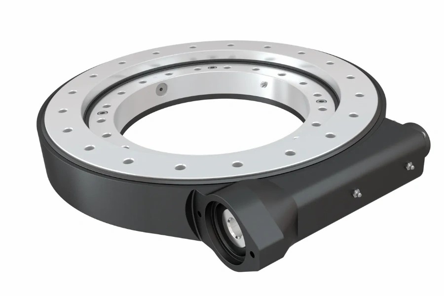
What is a slew ring bearing for robotics? It is a large-diameter rotary bearing, often with an integral gear, that carries axial, radial, and tilting loads on a robot base, turntable, or positioner axis. The question maintenance teams ask is narrower. How far out of flat, or out of center, can the mounting be before the ring starts to bind, wear unevenly, or lose repeatability?
No single number answers that for every ring. The limit lives on the bearing drawing, and it depends on ring section, preload, and load. What you can do is read the symptoms in the right order and measure the right points. This article gives that order.
Symptoms First, Causes Second
Start by writing down what you observe, not what you suspect. "Uneven torque" is an observation. "Mounting distortion" is a guess until you have measurements.
Misalignment is only one of several possible causes. The table below keeps the symptom and the possible causes separate.
| Observed symptom | Possible causes (not yet confirmed) | First thing to check |
|---|---|---|
| Torque peaks at the same angle every revolution | Local high spot on the mounting face, off-center pilot, tight gear mesh point | Torque-to-rotate with the drive disconnected |
| Wear or fretting on one side of the raceway or gear | Tilted axis, uneven load path, flatness error | Wear position relative to load direction |
| Repeatability drifts after a few hours of running | Bolt relaxation, thermal change, backlash that varies around the ring | Bolt torque and backlash at several angles |
| Grinding noise or metal particles in grease | Raceway damage, contamination, severe binding | Stop and inspect grease before running again |
Stop condition: if you hear grinding, or find bright metal flakes in the grease, stop the axis. Running on a damaged raceway turns a fixable mounting problem into a replacement.
Preliminary Checks Before You Loosen Anything
These checks need no disassembly. Do them in this order, because each one narrows the next.
- Review recent changes. Look for a replaced ring, re-welded structure, a collision, or re-tightened bolts. A problem that started right after a change points to that change first.
- Measure torque-to-rotate. Disconnect the drive if you can and turn the axis slowly by hand or with a torque wrench. Note the angle of any peak.
- Check the bolts. Look for missing, loose, or unevenly torqued fasteners. Compare against the bolt grade and torque on the drawing.
- Inspect the grease. Note color, texture, and any particles. Dark, gritty grease points toward wear that has already started.
- Check backlash at several angles. If it changes a lot around the ring, concentricity of the gear side is a suspect.
Read the result like this. A tight spot that stays at one fixed angle suggests a geometric cause, such as a high spot or off-center pilot. A tight spot that moves with load direction suggests a load or tilt problem instead. Uniform stiffness all the way around points away from mounting geometry, toward preload, seals, or grease.
Request Your Custom Slew Drive or Bearing Spec
Tell us your load, speed, and environment — receive a tailored 100–5000 mm slewing drive or slewing bearing proposal with 3D drawings within 24 hours.
Flatness and Concentricity Conditions Where a Robotic Slew Ring Starts to Bind
A slewing ring is a thin, flexible section compared with the structure under it. When bolted down, it follows the mounting surface. A flatness error on the base becomes a bend in the raceway, and that bend shows up as binding, uneven wear, or drift.
We do not publish one universal tolerance here. Flatness and concentricity limits depend on the ring type and size. The reference you need is the flatness and concentricity requirement on the bearing drawing for your exact model. If you have a slewing bearing from us, ask for those values with the model number.
| Condition | How to measure | What you may observe | Likely consequence | Action |
|---|---|---|---|---|
| Local high spot on mounting face | Feeler gauge or straightedge under the ring before bolting | Gap on one side, torque peak at one angle | Raceway pinched, local wear | Correct the face. Do not shim to "average" it. |
| Bolt-pull distortion | Dial indicator on the ring face while tightening bolts in stages | Reading moves as bolts are torqued | Ring is being forced flat, so preload rises | Stop. Compare reading with drawing limit. |
| Dish or wave across the diameter | Straightedge or indicator sweep across the face | Uniform stiffness change, early fatigue | Uneven load sharing on raceway | Re-machine or re-grind the interface. |
| Off-center pilot or bore | Indicator on the pilot diameter while rotating | Backlash varies around the revolution | Gear mesh binds and wears on one arc | Re-center the ring or correct the pilot. |
| Axis tilt | Face runout after the ring is mounted and rotated | Wear on one side, repeatability drift | Edge loading, positioning error | Check the structure and mating flange. |
Where the limits stop applying. A ring with a heavier section tolerates more mounting error than a compact one, because it is stiffer. A light, thin ring, like a light load slewing bearing or a compact crossed roller design, follows the surface more closely. That is why a slew ring bearing for robotics that needs tight repeatability often has the strictest mounting requirements.
When to stop measuring: if the measured value is outside the drawing limit, the structure needs correcting. More bolt torque or extra shims will not fix it. Escalate with your readings.
Matching Cause to Action, Then Checking the Result
Do not apply one remedy to every case. Link each cause to the evidence that supports it, the action that follows, and a check that proves it worked.
| Likely cause | Distinguishing evidence | Corrective action | Result check |
|---|---|---|---|
| Mounting-face high spot | Feeler gauge gap; torque peak at fixed angle | Correct the face, then remount | Torque-to-rotate curve is flatter around the ring |
| Off-center pilot | Indicator runout; backlash varies by angle | Re-center or correct the pilot | Backlash is even at several angles |
| Bolt relaxation | Torque loss at re-check; drift after hours of running | Re-torque in a star pattern, in stages | Repeatability holds over a full shift |
| Contamination or lubrication | Gritty grease; uniform roughness all around | Clean, inspect, regrease per the drawing | Smooth rotation with no particles after run-in |
Illustrative example. Say a robotic turntable shows a torque peak at about the same angle each turn. Torque is normal after the drive is disconnected, except at that angle. A feeler gauge shows a gap under the ring at the same position. That points to the base flange. After the face is corrected and the bolts are re-torqued in stages, the same torque test should show the peak gone. If it is not, the diagnosis was incomplete and you keep looking.
The same logic matters on batch builds. Take the Manchester, UK automation equipment manufacturer that ordered 100 units of SP-I Slew Drive model SP-I 0841-32.1 for automated turntable systems. When one fixture design repeats 100 times, a flatness error in that fixture repeats too. Measuring the first-article base before building the rest is cheap insurance.
Common Mistakes That Hide the Real Cause
- Using shims to "average out" a gap instead of correcting the face.
- Tightening bolts harder to pull the ring flat. This adds preload and raises torque.
- Measuring flatness only after bolting, when the ring is already distorted.
- Tightening bolts in a circle rather than a star pattern.
- Replacing the ring without checking the base. The new ring then inherits the same problem.
- Blaming the ring when the cause is motor tuning or controller backlash compensation.
Prevention and When to Escalate
Prevention is mostly record keeping. Measure flatness and pilot runout at first article, save the torque-to-rotate baseline, and record bolt torque and sequence. When a symptom appears later, you compare against a baseline instead of guessing.
Recurrence checks are simple:
- Re-check bolt torque after the first run-in period.
- Repeat the torque-to-rotate test at set maintenance intervals and log the peaks by angle.
- Inspect grease color and particles at every service.
- Re-measure the base after any structural weld, repair, or impact.
Escalate when: measurements exceed the drawing limit, the tight spot persists after the bolts are loosened, grease shows metal particles, or the raceway shows visible marks. At that point further tries by trial and error risk damage.
When you contact us, send the following so the review starts fast:
- Bearing or slew drive model and drawing number
- Photos of the mounting face, the ring, and the grease
- Flatness and runout readings, plus the torque-to-rotate curve by angle
- Bolt grade, torque value, and tightening sequence
- Load cycle, speed, and environment, including washdown or dust
- Date of the last structural change or collision
Luoyang Slewing Bearing Co., Ltd. works under an ISO 9001:2015 quality system. Each slewing bearing we ship passes CMM three-coordinate inspection, which is how we verify our own geometry. You can read more about slew drive quality control on our site. We respond to technical questions within 48 hours. Confirmed manufacturing defects are replaced free, and our 2-year extended quality warranty applies. If the evidence points to the mounting structure instead, we will say so and show you the measurement.
Sometimes the mounting interface cannot be corrected, for example when the structure is fixed and the flange is too far out of limits. In that case, a customized slew drive with a revised interface may be the better route. Customized orders start at 5 sets, and standard products start at 1 set, so you can test one before committing.

Request Your Custom Slew Drive or Bearing Spec
Tell us your load, speed, and environment — receive a tailored 100–5000 mm slewing drive or slewing bearing proposal with 3D drawings within 24 hours.
 WhatsApp

 +8613903880726