



What is a slew ring bearing? It is a large-diameter bearing that carries axial load, radial load, and tilting moment at the same time while one structure rotates against another. In a robot, it usually sits in the base, shoulder, or turntable joint. If you are chasing lost repeatability, a slew ring bearing for robotics is one of the first places to look, because every small error at that joint is multiplied by the reach of the arm.
The short answer: backlash causes direction-dependent error, axial runout and mounting flatness cause tilt-dependent error, and all three grow with arm length. You need to budget them together, not read each number on its own. This article shows how, using a worked example and a checklist you can use before prototype validation.
How Backlash, Axial Runout, and Mounting Flatness Combine Into End-Effector Position Error
Each error enters the arm in a different way. Backlash is lost motion in the rotation direction. Axial runout is wobble of the rotating ring along the axis. Mounting flatness is how well the supporting surface lets the ring sit true. The end-effector sees the sum.
The basic geometry is simple. Tip error is roughly the angular error in radians multiplied by the distance from the joint to the tool point. A small angle gets large fast on a long arm.
| Error source | How it reaches the tool point | Error pattern | Illustrative value* | Tip error at 1,200 mm reach* |
|---|---|---|---|---|
| Backlash (gear mesh or internal play) | Rotation angle lost when direction reverses | Appears on reversal; changes with load direction | 0.05° (about 0.00087 rad) | about 1.05 mm |
| Axial runout | Rotating ring tilts the arm as it turns | Cyclic with rotation angle | 0.05 mm at a 400 mm measuring diameter (about 0.000125 rad) | about 0.15 mm |
| Mounting flatness | Ring is pulled out of plane by bolts, adding a fixed tilt and raceway distortion | Fixed offset plus extra runout | 0.10 mm over a 400 mm span (about 0.00025 rad) | about 0.30 mm |
| Worst-case stack | Linear sum of the three | Combined | - | about 1.50 mm |
*These numbers are an illustration of the math, not product specifications. Replace them with your own measured or drawing values.
Two lessons come out of this table. First, backlash dominates in this example, about 70% of the stack. Second, the tilt errors are small alone but are not free, and a poor mounting surface hurts twice: it adds fixed tilt and it raises runout.
The patterns also differ in how fixable they are. Runout and flatness errors repeat at each angle, so calibration can map part of them out. Backlash on a reversing move is much harder to compensate, because it depends on load direction, wear, and friction.
What Each Specification Really Affects, and Where "Tighter" Stops Helping
A smaller number on a datasheet is not automatically better. Each parameter has a cost, and the cost shows up somewhere else in the joint.
| Parameter | What it affects in the robot | Trade-off of pushing it tighter | Best fit |
|---|---|---|---|
| Backlash | Reversal error, settling, limit-cycle hunting in the control loop | Less clearance raises friction, torque draw, and heat, and can speed up wear | Pick-and-place, inspection, and fine positioning with frequent reversals |
| Axial runout | Tool height and tilt that change with joint angle | Tighter grades cost more and need a stiffer, flatter mounting surface to be worth it | Tall or long-reach arms, vision-guided tasks |
| Mounting flatness | Fixed tilt, raceway distortion, uneven load sharing | Grinding or machining the base adds cost; a thin base may still deflect | Any joint where bolts clamp the ring to a fabricated frame |
| Preload / internal clearance | Tilting stiffness and play under moment load | Higher preload gives stiffer motion but raises starting torque | Joints with large overturning moment from the arm |
One distinction matters for buyers. A bearing alone has internal play, while a geared slew ring or a slew drive adds mesh backlash on top. When a supplier quotes "backlash," ask which one they mean. For geared joints, a Slew Drive combines the bearing, gear, and housing, so you can specify the whole chain together.
Bearing type matters for tilt stiffness too. Crossed Roller Slewing Bearings are commonly chosen when compact size and moment stiffness both matter. Ball types can suit lighter loads. The right pick depends on your moment load, which only your arm geometry can tell you.
Request Your Custom Slew Drive or Bearing Spec
Tell us your load, speed, and environment — receive a tailored 100–5000 mm slewing drive or slewing bearing proposal with 3D drawings within 24 hours.
How Load, Gear Type, and Environment Change the Error Budget
Catalog accuracy is measured under set conditions. Your robot adds moment load, temperature swings, dust, and thousands of duty cycles. Those conditions move the numbers.
Moment load tilts the ring elastically
The arm and payload create an overturning moment. Under that moment the ring and its mounting structure flex, so tilt under load can be larger than tilt measured at rest. The conclusion: size the ring and the base for the extended-arm, full-payload case, not the light-load case. The limit: if payload and reach are small, this effect may be negligible next to backlash.
Gear type decides how backlash behaves
A Worm Gear Slew Drive can be self-locking, which holds position when power is off. That helps a stationary joint under external load. It is less suited when high efficiency or fast back-driving is needed. A Double Worm Slew Drive uses two worms and can be arranged to take up lash, which is a reason to consider it when direction reversal is frequent. Check the actual adjustment method with your supplier before relying on that.
Wear changes backlash over life
Backlash is not fixed. It grows as gear flanks wear, and dust or moisture speeds that up. Our slew drives are offered with protection up to IP66 and anti-corrosion ratings up to C4H, with materials such as alloy steel, ductile cast iron, and stainless steel chosen for load, speed, and environment. If your robot works in a washdown or outdoor setting, that choice affects how long your accuracy lasts, not just how long the part survives.
Real precision figures from our customer work
These cases are not robot arms, but they show how angular precision gets specified in practice:
- A South Korean port equipment manufacturer placed a 20-unit repeat order of WEA9-62-25HR single worm slew drives for port crane systems, with tracking precision of 0.15° or better, IP65 sealing, and self-locking.
- A British Columbia forestry equipment manufacturer ordered 30 units of WED14-86-25BHR.5 double worm slew drives for grapple machines, with precision of 0.13° or better.
Both show angular precision stated as a drive-level requirement, together with sealing and locking behavior. Do the same for your joint: write the angle, the load condition, and the environment on one line of the spec.
Common Misunderstandings and What to Request Before You Release a Design
Most repeatability problems trace back to how the numbers were read, not to a defective part. These are the mistakes we see engineers make when comparing bearing accuracy.
- Choosing by catalog diameter only. Two rings with the same bolt circle can have very different runout and clearance grades.
- Comparing numbers measured differently. Runout quoted at a small diameter and runout at a large diameter are not equal. Ask for the measuring diameter.
- Treating backlash as a bearing-only number. In a geared joint, the mesh sets most of the reversal error.
- Ignoring the mounting surface. A precision ring bolted to a warped weldment loses its precision. Flatness is part of the bearing system.
- Assuming lower is always better. Near-zero clearance can overheat or stall a joint with a small motor.
Before prototype validation, request the following from any supplier:
- Backlash or clearance value, with measuring method, load direction, and position on the gear.
- Axial and radial runout values, with the measuring diameter.
- Required flatness and bolt-torque sequence for the mounting surfaces.
- Inspection records. At Luoyang Slewring Bearing Co., Ltd., every slew bearing passes CMM three-coordinate inspection and dynamic load testing, and our processes sit under an ISO 9001:2015 quality management system. See our Slew Drive Quality Control page for how inspection is done.
- Sealing rating and the material chosen for your environment.
Records establish what a part measured at the factory. They do not establish how it behaves after installation on your frame, so plan a check on your own assembly too.
A Step-by-Step Way to Build Your Position Error Budget
- Set the allowable tip error. Take the task tolerance and leave margin for the vision, tool, and control errors.
- Convert it to an angle. Divide by the maximum reach. For 0.5 mm at 1,200 mm, the angle is about 0.0004 rad, or about 0.024°.
- Allocate it. Give backlash the largest share if the joint reverses often, and assign smaller shares to runout and flatness.
- Check the base. Measure the mounting surface flatness. If it misses the target, machine it before blaming the ring.
- Test under load. Measure tip position at full reach and full payload, in both directions of travel.
- Decide what to compensate. Map repeatable tilt errors in software. Reduce backlash in hardware.
In the illustrative example above, a 1.5 mm worst-case stack would miss a 0.5 mm target by a wide margin. Cutting backlash alone from 0.05° to 0.015° would drop that term to about 0.31 mm, which brings the total near 0.76 mm. Reaching 0.5 mm would also need better flatness and runout. That is the point of an error budget: it shows which fix moves the result.
If your joint needs a non-standard bolt pattern, gear ratio, or housing, a Customized Slew Drive lets you define these around the error budget. Our standard-product MOQ is 1 set and the customized MOQ is 5 sets. We offer 3-day rapid prototyping, a technical proposal within 24 hours, and a 9-day standard production cycle, so a test unit does not have to hold up your validation schedule. We back orders with a 2-year extended quality warranty and a 48-hour technical response. For plain bearing needs, browse our Slewing Bearing range.
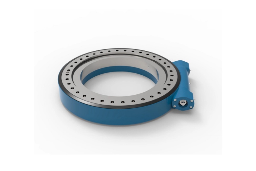
When you send an inquiry, include arm reach, payload, moment load, duty cycle, environment, and your target tip error. With those six items our engineers can respond with a matched proposal instead of a generic quote.
Request Your Custom Slew Drive or Bearing Spec
Tell us your load, speed, and environment — receive a tailored 100–5000 mm slewing drive or slewing bearing proposal with 3D drawings within 24 hours.
 WhatsApp

 +8613903880726