



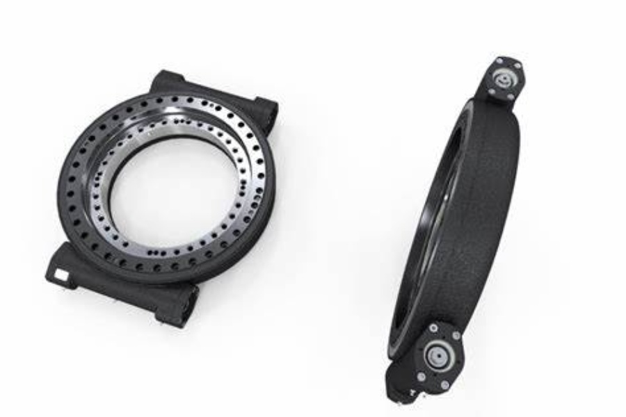
What is a slew ring bearing for robotics? It is a large-diameter bearing that carries axial load, radial load and tilting moment in a single ring set. A robot joint can then rotate without a separate shaft and bearing stack. The hard part is sizing it, because a waist joint and a shoulder joint load the same bearing in very different ways.
This guide is for design engineers who are defining a new robot axis or replacing a bearing that proved too small. By the end, you will have a load case, a tilt stiffness target, a backlash limit and a shortlist of bearing types you can send to a supplier. I draw on 30+ years of mechanical design work on heavy machinery and power transmission, including more than 200 equipment projects.
Inputs You Need Before Sizing Starts
Some inputs block progress. Others can be refined later. Sort them first so you do not stall on a number that does not change the result.
| Input | Blocks sizing? | Why it matters |
|---|---|---|
| Payload mass and reach at full extension | Yes | Sets axial load and tilting moment |
| Arm mass and center of gravity position | Yes | Often adds more moment than the payload does |
| Joint axis orientation (vertical or horizontal) | Yes | Decides whether gravity is axial or radial |
| Repeatability target at the tool tip | Yes | Converts to an angular backlash limit |
| Peak acceleration and emergency stop loads | Can wait for a first pass | Adds a dynamic factor on top of static loads |
| Envelope: outer diameter, bore for cables, height | Can wait for a first pass | Limits which bearing series fit |
| Environment (dust, washdown, temperature) | Can wait for a first pass | Affects seals, coating and material |
If the arm mass is still unknown, use a CAD mass estimate and mark it as a placeholder. A wrong guess of 20% is easier to fix now than after a prototype arrives.
Step-by-Step Selection Procedure
- Draw the worst-case pose. This is usually the arm fully extended and horizontal. Mark every mass and its distance from the bearing center.
- Calculate axial force, radial force and tilting moment. Axial and radial force come from weight (mass × 9.81). Moment is each force times its lever arm to the bearing center plane. Checkpoint: the sum of moments from the arm and the payload should match your CAD center-of-gravity result within a few percent.
- Add dynamic loads. Include acceleration of the payload and the arm. Ask your supplier which load factor they apply to their static rating.
- Convert the repeatability target to a backlash limit. Tip error ≈ reach × tan(angular backlash). At 1,000 mm reach, 0.1° of backlash gives about 1.75 mm of tip error. If your target is tighter than that, backlash or preload becomes the controlling requirement.
- Pick a bearing type. Use the type table in a later section. Start with the smallest cross-section that handles the moment, then check stiffness.
- Check the mounting structure. A stiff bearing on a thin, flexible flange will still tilt. Confirm flatness and bolt pattern with the supplier before releasing drawings.
- Pair it with the drive. Decide if you need a bearing with external gear teeth or an integrated slew drive. This sets how backlash is controlled.
Worked example (illustrative numbers, not a customer case)
Say the arm weighs 60 kg with its center of gravity 0.5 m from the base. The payload is 20 kg at 1.0 m. At the waist, axial load is (60 + 20) × 9.81 ≈ 785 N. Tilting moment is (60 × 0.5 + 20 × 1.0) × 9.81 ≈ 490 N·m.
Those are static values only. Multiply by the dynamic factor your supplier gives you, then compare to the bearing's rated capacity curve, not just one number from a catalog table.
Request Your Custom Slew Drive or Bearing Spec
Tell us your load, speed, and environment — receive a tailored 100–5000 mm slewing drive or slewing bearing proposal with 3D drawings within 24 hours.
Waist vs. Shoulder Joints: Load, Moment, Stiffness and Backlash Matrix
Most product pages describe a slew ring bearing for robotics as a waist component and stop there. The shoulder joint is just as common, and it asks for different things. The table below shows how the requirements shift.
| Selection factor | Waist joint (vertical axis) | Shoulder joint (horizontal axis) | Action for the designer |
|---|---|---|---|
| Main load path | Weight acts along the axis, so it is mostly axial | Weight acts across the axis, so it is mostly radial | Size the bearing's axial or radial rating accordingly |
| Tilting moment source | Arm and payload reach out from the base | Link center of gravity offset from the bearing plane | Calculate moment from the offset, not just from the payload |
| Tilt stiffness need | High, because tilt multiplies at the tool | High, and it also affects joint alignment | Compare stiffness data, not only load ratings |
| Backlash effect | Shows up as angular error at the tip | Same error, plus reversal when gravity torque changes sign | Set a backlash limit from the tip error formula |
| Gravity torque on the drive | None about the rotation axis | Large and one-directional at most poses | Size the drive for holding torque at the shoulder |
| Typical starting bearing type | Crossed roller or double-row ball for moderate loads; three-row roller for heavy loads | Crossed roller for compact, stiff joints | Treat as a first guess and verify with the load curves |
| Common failure sign | Wobble at full reach, raceway wear on one side | Lash on direction change, uneven wear in the loaded zone | Inspect for lash and one-sided wear at first service |
Where this does not apply: offset-axis joints, counterbalanced arms and parallel-link robots break these patterns. For those, run the full load case instead of relying on the table.
In the worked example above, a shoulder bearing with a 0.15 m offset would see about 785 N × 0.15 m ≈ 118 N·m of moment. The 490 N·m gravity torque would mostly go through the drive, not the bearing.
Which Bearing Type Fits Which Joint
Different designs trade stiffness, height and cost. Here is a quick comparison of the types most robot designers consider.
| Bearing type | Best fit | Limit |
|---|---|---|
| Single Row Slewing Ring Ball Bearings | Light to moderate loads, compact axes | Lower tilt stiffness than roller types |
| Double Row Ball Slewing Ring Bearing | Higher axial and moment loads with a moderate height increase | Needs a larger envelope than a single row |
| Crossed Roller Slewing Bearings | Compact joints needing high stiffness and low tilt | Sensitive to mounting flatness |
| Three-row Roller Slewing Bearings | Heavy payloads and large moments | Larger, heavier and costlier than most robot axes need |
For light arms, a light load slewing bearing may be enough. If the supplier cannot give you a stiffness figure for the series, ask for one before you commit.
Common Mistakes and How to Recover
- Sizing from payload only. The arm's own mass often adds as much moment as the payload. Recover by redoing the moment sum in step 2 with every link included.
- Using axial rating for a shoulder joint. A horizontal axis turns weight into radial load. Recheck against the radial and moment capacity curve.
- Ignoring backlash until testing. You see it as tip scatter on direction reversal. Go back to step 4 and recalculate with the actual reach.
- Mounting on a thin flange. You see uneven wear or tilt at full reach. Stiffen the structure or add a thicker adapter ring.
- Skipping the seal and coating review. Dust or washdown can shorten life. Match protection to the site before you finalize the part number.
Completion check
You are done with selection when each item below is true:
- Axial, radial and moment loads are written down for the worst-case pose, with dynamic factors added.
- The supplier's capacity curve shows margin over those loads.
- Tip error from backlash is below your repeatability target.
- The mounting structure flatness and bolt pattern are confirmed.
- The drive option is chosen: bearing with gear teeth, or an integrated slew drive.
Variations That Change the Procedure
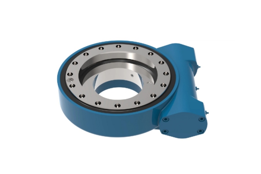
If you need tight backlash control and compact packaging, an integrated slew drive may replace the separate bearing and gear. The double worm slew drive design is one route to lower backlash, because two worms can be set against each other. For non-standard bolt patterns or cable bores, a customized slew drive is often more practical than redesigning the robot base.
Luoyang Slewring Bearing Co., Ltd. has built slewing bearings and slew drives for over 15 years, and its products have been used on 2,000+ heavy-equipment projects. None of the cases below are robot arms, but they show comparable load paths and precision demands:
- A Manchester, UK automation equipment manufacturer ordered 100 units of SP-I 0841-32.1 for automated turntable systems.
- A British Columbia, Canada forestry equipment maker ordered 30 units of WED14-86-25BHR.5 double worm slew drives, with precision of 0.13° or better.
- A Houston, Texas manufacturer ordered 100 units of SEA21-125-25HR(2) for slewing platforms.
For a prototype, a standard product MOQ is 1 set and a customized product MOQ is 5 sets. We offer 3-day rapid prototyping and send a technical proposal within 24 hours. The factory is ISO 9001:2015 certified, and every slewing bearing goes through CMM inspection and dynamic load testing. See our slew drive quality control page for details. Our 2-year extended warranty covers confirmed manufacturing defects.
If you are replacing an undersized part, send your load case, envelope and backlash target. Our engineers will check the numbers against the right series and tell you where the slew ring bearing for robotics you picked has margin, and where it does not.
Request Your Custom Slew Drive or Bearing Spec
Tell us your load, speed, and environment — receive a tailored 100–5000 mm slewing drive or slewing bearing proposal with 3D drawings within 24 hours.
 WhatsApp

 +8613903880726