



Engineers often ask how to select the right slew drive for a new project. The most common mistake I see is focusing only on the output torque listed in a catalog. This approach overlooks the complex combination of forces that a drive must handle in the real world, often leading to undersized units, premature wear, and unexpected failures. True sizing requires a more complete analysis of your application's specific load case.
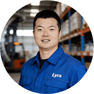
My name is Lewis, and I’ve spent over 30 years in heavy machinery design. I've learned that a successful integration starts with breaking down the loads. You must separately calculate the running torque, holding torque, axial load, radial load, and the critical overturning moment. Only when you have these five values can you confidently select a slewing drive that will deliver the required performance and service life.
This guide provides a structured sequence for translating your application's forces into a correctly sized unit. It's the same process we use when developing technical proposals for our clients' heavy-equipment projects.
A Step-by-Step Sizing Sequence for Accurate Selection
Selecting a drive based on a single torque value is a recipe for problems. The forces acting on a rotational system are multi-directional. A gearbox might have enough power to rotate a load (running torque) but lack the structural strength to resist being pried off its foundation by wind or gravity (overturning moment). Follow these steps to build a complete load profile.
-
Calculate All Static and Dynamic Loads: Before looking at any gearbox, quantify the forces it must withstand.
- Axial Load (Fa): The force acting parallel to the axis of rotation. For a crane, this is the weight of the boom, counterweight, and the lifted load.
- Radial Load (Fr): The force acting perpendicular to the axis of rotation. This is often generated by side winds or inertia during acceleration and deceleration.
- Overturning Moment (M): The tilting force that tries to lever the drive off its mounting base. It's calculated by multiplying a force (like wind or the load's weight) by its distance from the drive's centerline. This is often the most underestimated and damaging load.
- Determine Required Running Torque: This is the torque needed to initiate and sustain rotation at the desired speed and acceleration. It must overcome the load's inertia and any frictional resistance in the system. Your calculation should account for the mass being moved and how quickly it needs to accelerate.
- Define Holding Torque Requirements: This is the static torque capacity required to hold a load stationary against external forces, such as high winds acting on a solar panel or a marine crane's boom on a rolling sea. For many applications, the required holding torque is significantly higher than the running torque. A Worm Gear Slew Drive is often preferred in these scenarios due to its natural self-locking characteristics, which help resist back-driving.
- Cross-Reference with Manufacturer Load Curves: With your calculated values (Fa, Fr, M, running torque, holding torque), you can now evaluate a manufacturer's datasheet. Do not just look at the maximum torque. You must find the performance curve that shows the combined load capacity. Your specific combination of Axial Load and Overturning Moment must fall within the safe operating area of the curve.
- Apply a Safety Factor and Select Gear Ratio: Always apply a safety factor to your calculated loads to account for unforeseen shock loads, gusts of wind, or operational variances. The appropriate factor depends on the application's predictability and risk. Finally, choose a gear ratio that delivers your desired output speed from your chosen input motor (hydraulic or electric).
By following this sequence, you ensure the selected drive is robust enough to handle every aspect of the load, not just the rotational force.
Common Sizing Mistakes and How to Avoid Them
Over three decades, I've seen the same sizing errors cause costly field failures. Being aware of these common pitfalls during the design phase is the best way to prevent them. Here are the top mistakes to avoid.
- Mistake 1: Ignoring the Overturning Moment. This is the single most common cause of failure. An engineer might select a drive with sufficient output torque, but a high overturning moment can cause gear tooth deflection, brinelling of the bearing raceways, and eventual catastrophic failure. How to Avoid: Always calculate the maximum possible overturning moment and ensure it falls well within the limits shown on the manufacturer's load curve. For example, our WED series Double Worm Slew Drive units are selected for applications like forestry grapples and heavy steering systems precisely for their high moment capacity. A Canadian forestry equipment manufacturer uses our WED14 units specifically for their ability to handle the intense twisting forces on grapple machines.
- Mistake 2: Sizing Based on Motor Torque Alone. The motor provides the input, but the gearbox must handle the output forces. A powerful motor paired with an undersized gearbox will simply destroy the gearbox. How to Avoid: Size the gearbox for the load first, then select a motor that can provide the necessary input torque and speed for the chosen gear ratio.
- Mistake 3: Underestimating Environmental Factors. Wind is a major source of unexpected torque and overturning moments, especially in applications like solar trackers and satellite dishes. Dust, moisture, and corrosive salt spray can also lead to premature failure if the unit's sealing and coating are inadequate. How to Avoid: Specify the operating environment. For a utility-scale solar project in a US desert, we supplied 50 units of our SP-I Slew Drive with an IP65 protection rating to prevent dust ingress. For marine cranes, like those for UK Ocean Marine Systems, we provide units with IP66 sealing and C4H anti-corrosion ratings.
- Mistake 4: Neglecting Duty Cycle and Thermal Limits. A drive rated for intermittent use will overheat and fail if run continuously. The heat generated during operation must be able to dissipate. How to Avoid: Clearly define the duty cycle (minutes on vs. minutes off) and consult the manufacturer's thermal rating to ensure the unit can operate within safe temperature limits for your application.
Request Your Custom Slew Drive or Bearing Spec
Tell us your load, speed, and environment — receive a tailored 100–5000 mm slewing drive or slewing bearing proposal with 3D drawings within 24 hours.
Matching Drive Technology to Your Load Profile
The type of gearing inside the unit directly impacts its performance characteristics. The choice between a single worm, double worm, or spur gear design depends entirely on the application's torque, precision, and efficiency requirements. There is no single "best" type; there is only the best fit for your specific load case.
Our experience across more than 2,000 heavy-equipment projects shows a clear pattern in which technologies are chosen for certain jobs. The table below summarizes the key trade-offs.
| Drive Type | Key Characteristics | Best-Fit Applications | Real-World Example |
|---|---|---|---|
| Single Worm (WEA/SEA Series) | High gear ratio, high torque multiplication, self-locking to resist back-driving, smooth rotation. | Cranes, manlifts, and platforms that must hold a position under load. | A South Korean port equipment manufacturer uses our WEA9 drives for port crane systems, where the self-locking feature and ≤0.15° tracking precision are essential for safety and stability. |
| Double Worm (WED Series) | Extremely high holding torque, increased contact area for shock load resistance, zero backlash options available for high precision. | Heavy-duty rotating modules, mining equipment, and forestry machinery with high shock and overturning loads. | An Australian heavy equipment client specified our HWE21 double worm drives for mining excavators to withstand the intense shock loads during digging. |
| Spur Gear (SP Series) | High mechanical efficiency (>95%), low backlash, suitable for continuous rotation and high-speed applications. Not self-locking. | Solar trackers, industrial automation turntables, and satellite antenna positioners requiring constant adjustment. | Our SP-I series spur gear drives are used in large-scale solar projects across South America to boost energy yield by up to 40% through precise, continuous sun tracking. |
Verifying Load Capacity and Reliability in Production
A well-designed slew drive is only as good as the materials and manufacturing processes behind it. At Luoyang Slewring Bearing Co., Ltd., we ensure our products meet and exceed their datasheet specifications through rigorous quality control, a core part of our ISO 9001:2015 certified system.
It starts with material selection. Depending on the working condition—load, speed, and environment—we utilize materials ranging from ductile cast iron to forged alloy steel. This ensures the foundational Slewing Bearing and gearing have the necessary hardness and toughness.
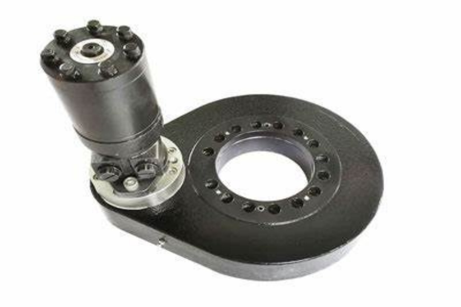
Every single unit we produce undergoes military-grade quality control. This is not just a final check. It's a process that includes:
- CNC Machining Centers: Ensuring high-precision manufacturing of all components, from the worm shaft to the slewing ring.
- CMM Three-Coordinate Inspection: Every critical component is dimensionally verified to ensure it meets design tolerances. This step is vital for achieving the high precision required by clients like a Canadian forestry equipment manufacturer, who relies on our drives for ≤0.13° precision.
- Dynamic Load Testing: As a final verification, we test the assembled drive under simulated load conditions to confirm its torque output and smooth operation.
This commitment to Slew Drive Quality Control allows us to maintain a failure rate below the 0.5% industry standard and confidently offer a 2-year extended quality warranty on our products. Whether you need a standard product (MOQ of 1 set) or a fully Customized Slew Drive, our engineering team can provide a technical proposal within 24 hours. We have successfully localized production of German-standard SE/WE series drives, offering performance that matches international brands at a 30-50% cost savings, a value recognized by clients from the USA to the Netherlands.
Ultimately, choosing the right drive is about matching a verified, high-quality product to a thoroughly analyzed load case. By moving beyond a simple torque number and embracing a complete load analysis, you build reliability and performance directly into your equipment from the very start.
Request Your Custom Slew Drive or Bearing Spec
Tell us your load, speed, and environment — receive a tailored 100–5000 mm slewing drive or slewing bearing proposal with 3D drawings within 24 hours.
 WhatsApp

 +8613903880726