



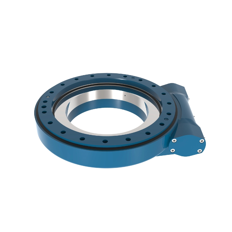
What is a slew drive? It is a compact rotary unit that combines a slewing bearing, gear ring, worm shaft, housing, and mounting interfaces to rotate and support a load around one axis.
The short answer is that slew drive design sets load capacity by controlling the path that axial force, radial force, and overturning moment take through the bearing ring, gear teeth, worm shaft, housing, and mounting bolts. A larger bearing alone does not guarantee a higher-rated assembly. The full structure must carry the same load without excessive contact stress, deflection, gear misalignment, or mounting distortion.
For early-stage specification, engineers should treat rated capacity as a combined-load question rather than a single vertical-load number. A drive that supports a centered platform may be unsuitable for the same platform with a long boom, offset payload, shock loading, or frequent reversing motion.
Start with the load condition rather than the drive size
Begin by separating the applied load into axial, radial, and overturning-moment components. This gives a usable starting point for comparing drive architectures and requesting a technical proposal. If one of these inputs is missing, a supplier cannot make a sound capacity assessment.
Axial load acts along the rotation axis. A horizontal turntable carrying a centered vertical payload is usually dominated by axial force. The rolling elements and raceways carry this force, while the housing and mounting structure transfer it into the machine frame.
Radial load acts perpendicular to the rotation axis. It often comes from side pull, wind force, boom movement, vehicle motion, or an off-center payload. Radial force can increase rolling-element contact stress and may shift the bearing ring relative to the worm mesh.
Overturning moment is usually the deciding load for a rotating platform with an offset center of gravity. It is created when force acts at a distance from the rotation center. Even a moderate vertical load can produce a high moment when the load is placed far from the bearing center.
| Load input | What it affects first | Practical consequence | When it may not govern |
|---|---|---|---|
| Axial force | Raceway contact and rolling elements | Sets the bearing's ability to support vertical thrust | May be secondary when the payload is strongly offset |
| Radial force | Raceway position, housing support, worm mesh alignment | Can increase wear and reduce smooth rotation | May be low on a fixed, centered vertical-axis table |
| Overturning moment | Opposed bearing contact zones, ring stiffness, bolts, housing | Can become the limiting condition for booms and cantilevered loads | May be low when the center of gravity stays close to the axis |
| Drive torque | Worm shaft, worm wheel teeth, motor or hydraulic input | Determines whether the unit can start, rotate, and hold the load | Must still be checked even when bearing capacity is adequate |
The conclusion is simple: specify the worst combined condition, not only the largest individual force. This approach fits crane platforms, solar trackers, forestry grapples, excavator attachments, and automated turntables. It does not replace fatigue or duty-cycle analysis when the machine rotates through repeated load cycles.
For applications where the bearing is selected separately from the drive, review the bearing architecture before finalizing the gearbox. A Slewing Bearing may be the primary structural element, while the worm drive provides rotation and holding torque. In an enclosed drive, the bearing, gear, housing, and mounting interfaces are engineered as one load-carrying system.
Follow the load path through the ring, worm, and housing
The useful way to judge capacity is to ask where each load goes after it enters the rotating structure. A properly supported load passes through several interfaces before reaching the base frame. Any weak interface can limit the assembly, even if the bearing raceway itself appears large enough.
| Load type | Primary path through the slew drive | Design feature that matters | What changes if it is undersized or flexible |
|---|---|---|---|
| Axial load | Upper mounting face → rotating ring → rolling elements and raceways → fixed ring → housing/base mounting face | Bearing raceway geometry, rolling-element arrangement, ring support, bolt pattern | Higher local contact stress, ring distortion, reduced bearing life, uneven load sharing |
| Radial load | Rotating structure → bearing ring and rolling elements → fixed ring → housing wall and machine frame | Radial guidance, housing stiffness, ring-to-housing fit, base-frame rigidity | Ring displacement can disturb gear contact and create uneven raceway loading |
| Overturning moment | Offset load → opposing zones of the bearing raceways → ring flanges and bolts → housing and base structure | Bearing diameter, raceway spacing, ring section, bolt support, mounting-face flatness | One side of the bearing becomes heavily loaded while the opposite side unloads |
| Rotational torque | Motor or hydraulic input → worm shaft → worm wheel or geared ring → rotating ring and load | Worm tooth contact, shaft support, housing alignment, lubrication | Tooth contact becomes concentrated, raising wear risk and reducing available output torque |
Axial force generally travels directly through the bearing raceways. The bearing may support this load efficiently when the mounting faces are flat and fully supported. A thin or uneven machine mounting plate changes the load path because the ring can flex rather than sharing force evenly around the circumference.
Radial force is more sensitive to housing and frame stiffness. The bearing controls relative motion between the rings, but the housing must keep the fixed ring in position. If the housing wall or base frame deflects, the worm and gear can move out of their intended contact position.
Overturning moment creates a different condition. It does not simply push downward; it tries to tilt one ring relative to the other. The bearing then carries concentrated load across opposed raceway zones, while mounting bolts and the housing react the separating and compressive forces.
The worm is mainly a torque-transfer component, not the primary route for platform weight. Yet it still affects rated performance because ring movement can alter tooth contact. A drive may have enough bearing capacity for a load but still require lower operating torque, slower acceleration, or a stiffer support structure to protect the worm mesh.
This distinction matters when comparing a Worm Gear Slew Drive with another rotation system. Worm gearing can provide compact reduction and self-locking behavior in suitable conditions, but it should not be assumed to resist every external load without checking the bearing and mounting arrangement.
For high moment loads or loads that can shift from side to side, a double-worm arrangement may improve torque distribution and rotational control. A Double Worm Slew Drive is relevant where a single input point could allow more torsional movement under changing load direction. It is not automatically the correct choice for low-load, low-duty applications where a simpler arrangement meets the actual requirements.
Request Your Custom Slew Drive or Bearing Spec
Tell us your load, speed, and environment — receive a tailored 100–5000 mm slewing drive or slewing bearing proposal with 3D drawings within 24 hours.
Understand which design parameters limit capacity in practice
Several parameters interact, and increasing one does not remove every other limit. Bearing diameter, raceway arrangement, gear geometry, housing stiffness, bolt support, and material selection must be assessed together. The best design is the one that matches the real load case and duty cycle rather than the physically largest unit.
Bearing diameter and raceway spacing
A larger bearing diameter can improve resistance to overturning moment because the load is reacted over a wider circle. Greater spacing between opposing load zones can reduce the force required at each local contact area for a given moment. This is useful for cantilevered booms, elevated work platforms, and wide rotating tables.
The limit is installation space and structural support. A larger ring mounted on an undersized or flexible base does not deliver its expected advantage. The machine frame must provide continuous, stable support near the mounting interface.
Rolling-element and ring configuration
The rolling-element arrangement determines how the bearing accepts combined loads. Ball-based arrangements can suit many compact rotation duties, while roller arrangements may be considered when the load pattern and application call for higher structural load handling. Selection must be based on the actual axial, radial, and moment combination rather than a product name alone.
For example, a Three-row Roller Slewing Bearings configuration separates load paths more clearly than simpler arrangements. That can be useful for demanding combined-load machinery. It is not necessarily appropriate for a light-duty positioning system where compact size, lower weight, and cost are the main requirements.
Worm mesh and output torque
The worm shaft and worm wheel must transmit enough output torque to start and rotate the load under the highest expected resistance. Resistance can include gravity effects from an offset center of gravity, friction, wind-induced force, acceleration, and process loads. A capacity check should therefore include both static holding condition and motion condition.
More reduction can increase output torque, but it also changes speed and may affect efficiency. Do not compare output torque values without confirming the operating speed, input conditions, duty cycle, and load direction. A slow solar tracker and a frequently reversing industrial turntable place different demands on the same basic mechanism.
Housing, mounting bolts, and machine frame
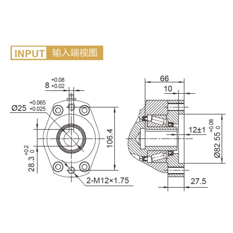
The housing connects the fixed bearing ring to the customer’s base structure. Its role is to preserve ring position, support the gear mesh, and transfer loads through the mounting bolts. Housing stiffness is especially relevant when radial load and overturning moment occur together.
Material should match the working condition. Luoyang Slewring Bearing Co., Ltd. selects from ductile cast iron, alloy steel, stainless steel, and forged alloy steel according to load, speed, and environment. This does not mean one material is always superior; corrosion exposure, cyclic load, machining requirements, and structural rigidity all affect the choice.
Use a combined-load check before approving an architecture
A practical approval process prevents a common error: selecting a drive from one capacity figure shown without the related load condition. Ask for the rating context and provide the supplier with the information needed to check the full assembly. This is appropriate for new equipment, replacement drives with changed duty, and customized rotating mechanisms.
- Define the rotating mass and center of gravity. State the total mass, the horizontal distance of the center of gravity from the rotation axis, and whether the center shifts during operation.
- List external forces. Include vertical process load, side pull, wind, boom reaction, braking force, and any impact or vibration source that can enter the rotating structure.
- Identify the worst positions. A boom may create its highest moment at full reach, while a rotating table may see its highest radial load during acceleration or material transfer.
- Set rotation requirements. Provide output speed, direction changes, start-stop frequency, required holding condition, and expected service hours.
- Describe the mounting structure. Share mounting dimensions, support-face design, bolt arrangement, available envelope, and frame material where possible.
- Request a combined-load review. Ask the supplier to confirm the bearing, worm set, housing, and mounting assumptions rather than supplying only a model number.
- Verify the delivered unit. Review inspection and test records that apply to the specified product and application requirements.
The conclusion is that the rotating load must be converted into forces and moments before model selection. This process fits early design validation. It does not eliminate the need for machine-level verification when the final frame, weldment, or attachment can alter support stiffness.
At Luoyang Slewring Bearing Co., Ltd., technical proposals can be provided within 24 hours when the application data is available. Standard product orders can start from one set, while customized products have a five-set minimum order quantity. This can help engineering teams validate a sample before committing to a broader equipment build.
Avoid capacity mistakes that lead to the wrong drive selection
The most costly mistakes usually come from treating one rating as a complete description of performance. The following checks help purchasing teams and engineers compare proposals on the same basis.
- Using only payload weight: A centered vertical payload may look acceptable, but an offset center of gravity creates overturning moment. Include the distance from the rotation axis before approving a model.
- Ignoring radial force: Side loads can displace the ring and affect worm engagement. Check boom side pull, cable tension, wind force, and vehicle movement when they apply.
- Assuming self-locking solves all holding risks: Self-locking behavior is application-dependent. Confirm the actual load direction, vibration, shock condition, and safety requirements for the equipment.
- Comparing ratings from different duty conditions: Static load capacity, dynamic operating load, and gear output torque answer different questions. Request the condition behind each value before comparing suppliers.
- Neglecting the mounting frame: A capable drive installed on an unsupported or warped interface can suffer uneven bearing loading. Review the machine support surface and bolt pattern with the drive supplier.
- Choosing a larger drive without checking speed: Larger units may affect available installation space, rotation speed, input requirements, and machine weight. Select for the duty, not for size alone.
A real application illustrates why load type matters. A South Korean port equipment manufacturer placed a repeat order for 20 WEA9-62-25HR single-worm slew drives for port crane systems. The stated requirement included self-locking operation, IP65 sealing, and tracking precision of no more than 0.15 degrees, showing that crane selection involves sealing, positioning, and holding behavior alongside structural loading.
Another example is a Canadian forestry equipment manufacturer that used 30 WED14-86-25BHR.5 double-worm slew drives for forestry grapple machines, with stated precision of no more than 0.13 degrees. A grapple can experience changing load direction and repeated movement, so selection should account for the operating cycle and changing load path instead of relying on a single static payload value.
Verify the supplier evidence behind the rated assembly
Capacity claims are more useful when they are tied to inspection, production control, and a stated application review. Ask whether the supplier can identify the bearing configuration, worm arrangement, housing material, protection requirement, inspection method, and warranty terms for the proposed unit. This is especially important when the drive will become part of a safety-sensitive or expensive machine.
Luoyang Slewring Bearing Co., Ltd. operates an ISO 9001:2015-certified facility with six production lines and an annual capacity of 100,000 sets. The company also offers CE marking for the European market and makes factory audit reports available on request. These points help buyers assess production controls, but they do not replace application-specific engineering validation.
For inspection, every slewing bearing is stated to undergo CMM three-coordinate inspection and dynamic load testing under the company’s quality-control process. The company provides a two-year extended quality warranty, a 48-hour technical response, and free replacement for confirmed manufacturing defects. Review the available Slew Drive Quality Control information alongside the project load data before releasing a purchase order.
For harsh outdoor equipment, also state the required environmental protection level. Luoyang Slewring Bearing Co., Ltd. offers slew drives with protection up to IP66 and anti-corrosion protection up to C4H. These features address exposure conditions, but they do not increase structural load capacity by themselves.
The final decision should confirm four linked items: the combined load case, required output torque, support-frame stiffness, and operating environment. When those inputs are documented, the selected drive architecture can be checked as an assembly rather than guessed from a catalog size.
Request Your Custom Slew Drive or Bearing Spec
Tell us your load, speed, and environment — receive a tailored 100–5000 mm slewing drive or slewing bearing proposal with 3D drawings within 24 hours.
 WhatsApp

 +8613903880726