



What is a configurable slew drive? It is a rotary drive assembly selected or adapted around the machine’s required load path, mounting arrangement, motor connection, protection needs, and available installation space. The drive may appear to be a small part of a larger machine, but its interfaces affect the frame, motor bracket, guarding, wiring route, and service access.
For concept-stage machine designers, the decision is rarely just “standard or custom.” The real decision is whether the selected unit can fit the final equipment layout without forcing late changes to steelwork, motors, cable paths, or protective covers. A slew drive customize project should therefore begin with the machine interfaces, not with a catalog model number alone.
Luoyang Slewring Bearing Co., Ltd. supplies Slew Drive, slewing bearing, and customized slew drive solutions for industrial equipment. Our engineering team can provide a technical proposal within 24 hours, while rapid prototyping can be completed in as little as 3 days when the required design inputs are clear. That speed is useful only when the OEM and supplier agree on the interfaces early.
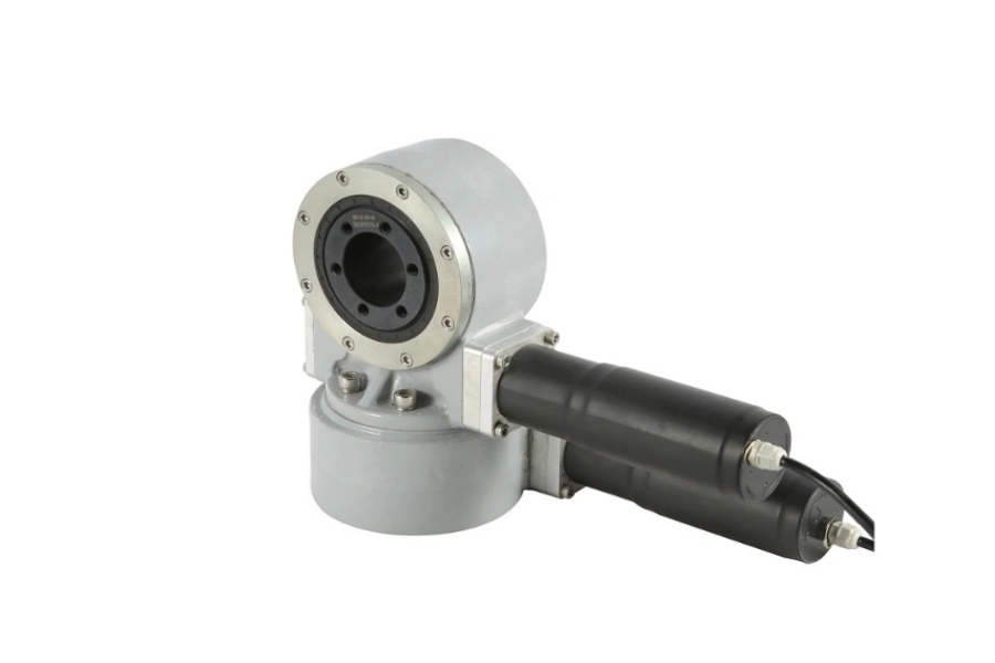
Start with the machine constraint that can cause the most rework
The first design task is to identify which fixed condition cannot move. In some machines, it is the main mounting plate. In others, it is the motor location, the cable exit direction, or a guard that must remain outside the rotation envelope. The least flexible condition should guide the drive selection.
A standard unit is often a sensible choice when the equipment frame can accept its mounting pattern, output orientation, motor position, and overall envelope without modification. This approach fits early prototypes that have generous installation space and do not need unusual motor or sealing arrangements. It is not the best route when the machine frame is already frozen or when a standard drive would require extra adapters that add height, weight, or possible alignment error.
A configured or customized unit is more appropriate when the surrounding machine has fixed geometry. Examples include a compact turntable inside a guarded automation cell, a crane attachment with limited motor clearance, or an outdoor tracker that needs a defined cable exit and environmental protection arrangement. In those cases, an OEM should send interface drawings before finalizing the drive type.
| Design condition | Recommended approach | Why it fits | Limit to check |
|---|---|---|---|
| Open layout with adaptable steel frame | Use a standard slew drive | Existing mounting and motor arrangements may reduce engineering work. | Confirm the standard envelope does not interfere with guards, hoses, or service areas. |
| Fixed mounting plate or existing machine frame | Review a customized mounting interface | It can reduce the need for spacer plates and secondary brackets. | Mounting-face dimensions, bolt locations, and load path still need engineering review. |
| Restricted motor-side clearance | Define motor interface before model release | The motor orientation may affect neighboring components and access for maintenance. | Do not assume a motor can be repositioned without verifying torque, shaft, and coupling requirements. |
| Outdoor, dusty, or marine exposure | Specify sealing and corrosion requirements early | Protection measures influence component selection and enclosure design. | Check the actual exposure, washdown method, temperature range, and chemical contact conditions. |
Do not treat the slew drive as an isolated gearbox. It is a load-bearing rotating assembly. The machine designer must show how axial load, radial load, tilting moment, rotation speed, duty cycle, and external forces reach the drive. If those inputs are incomplete, the supplier can discuss a concept, but final suitability cannot be confirmed.
Material selection should also follow the working condition. Luoyang Slewring Bearing Co., Ltd. works with ductile cast iron, alloy steel, stainless steel, and forged alloy steel depending on load, speed, and environment. A material choice should not be made from corrosion exposure alone; it must also suit the structural and transmission demands of the application.
Define mounting faces, motor interfaces, seals, and cable routes before the layout is frozen
Late-stage redesign usually starts with a small omission. The drive may fit the CAD envelope, yet the motor terminal box blocks a guard. A cable may need to cross a rotating area. A seal may need inspection access that the finished frame does not provide. These issues are easier to solve before procurement drawings are released.
For a slew drive customize request, the OEM layout team should issue an interface package that identifies fixed faces, clearances, motor details, environmental exposure, and cable-routing limits. This package gives the drive supplier a defined engineering handoff rather than a rough request for “a compact drive.”
| Interface to define early | Information to provide | How it prevents redesign | When more verification is needed |
|---|---|---|---|
| Mounting faces | Flatness expectations, bolt pattern, locating features, allowable envelope, and frame drawing. | Prevents adapter plates or frame changes after the drive is selected. | When the supporting structure has unknown stiffness or the load path is not yet modeled. |
| Motor interface | Motor model, mounting style, shaft details, brake needs, connector position, and service clearance. | Prevents motor interference with covers, hydraulic lines, or adjacent actuators. | When motor torque, control strategy, or coupling details remain undecided. |
| Seals and protection | Dust, water, salt exposure, cleaning process, storage conditions, and required protection target. | Allows sealing and coating requirements to be considered before enclosure geometry is fixed. | When exposure varies by region or the equipment will face chemicals not listed in the design brief. |
| Cable routing | Entry and exit direction, bend space, connector size, rotation range, and protection method. | Prevents cable clashes and avoids routing wires through inaccessible areas. | When rotating electrical components, encoders, or external control cabinets have not been selected. |
The mounting face deserves special attention. A drive can be properly manufactured and still perform poorly if it is mounted to a distorted or weak frame. The engineering team should provide the support plate drawing and describe whether the machine uses welded fabrications, machined surfaces, or separate brackets. This is especially relevant for heavy cyclic loads, where frame movement can affect alignment over time.
Motor interface planning should go beyond motor power. Ask where the motor body, brake, connector, and wiring gland will sit when the machine is at every operating position. A motor that fits in one CAD view may interfere after the rotating assembly reaches its full travel. This check is suitable for all compact equipment, but it does not replace electrical design review.
Seal selection should match the actual exposure rather than a general description such as “outdoor use.” Our slew drives can be specified with protection up to IP66 and anti-corrosion capability up to C4H. Those options may fit harsh industrial environments, but the final selection must be based on the application’s real dust, water, corrosion, and maintenance conditions.
Cable routing is often treated as a controls issue. It is also a mechanical issue. The drive, motor, frame, and cable protection hardware need enough clearance throughout rotation. If cable routing is not available through the assembly, the design team must decide early whether cables will remain stationary, move with the structure, or use a separate rotation-management solution.
Request Your Custom Slew Drive or Bearing Spec
Tell us your load, speed, and environment — receive a tailored 100–5000 mm slewing drive or slewing bearing proposal with 3D drawings within 24 hours.
Use a defined engineering handoff instead of exchanging incomplete drawings
The fastest path to a usable proposal is a short, organized technical package. This does not need to be a finished production drawing. It does need to identify the machine constraints that cannot change. Luoyang Slewring Bearing Co., Ltd. can provide a technical proposal within 24 hours, but proposal quality depends on the accuracy of the information supplied.
Recommended handoff sequence for OEM design teams
- Describe the application. State what rotates, what remains fixed, the expected duty cycle, and the equipment environment.
- Submit load and motion data. Provide axial load, radial load, tilting moment, rotation speed, rotation range, and the nature of repeated loading where known.
- Send the mounting-zone drawing. Include the available envelope, fixed faces, bolt areas, nearby parts, and service-access boundaries.
- Define the motor and control interface. Identify the selected motor if available, along with shaft, mounting, brake, connector, and orientation requirements.
- Identify protection needs. Explain dust, rain, washdown, salt exposure, storage, and expected maintenance practices.
- Review a proposed arrangement. Compare the supplier’s drawing with the full machine assembly, not only the local mounting zone.
- Approve a prototype before series release. Use a prototype to check physical fit, clearances, wiring access, and assembly sequence under actual equipment conditions.
This sequence fits equipment that is still in concept or prototype design. It is less effective when the machine frame has already entered production and cannot be changed. In that situation, the project may require a more restrictive configuration review, because the available options are determined by the existing geometry.
Luoyang Slewring Bearing Co., Ltd. supports sample orders for testing and evaluation. Standard products have an MOQ of 1 set, while customized products have an MOQ of 5 sets. This can help OEM teams validate fit and assembly before committing to a larger production schedule.
For assemblies requiring worm transmission and controlled holding behavior, a Worm Gear Slew Drive may be reviewed as part of the equipment concept. Where the load arrangement and operating demands call for a different transmission layout, a Double Worm Slew Drive may also be considered. Neither should be selected by name alone; the load case and interface limits remain the decision basis.
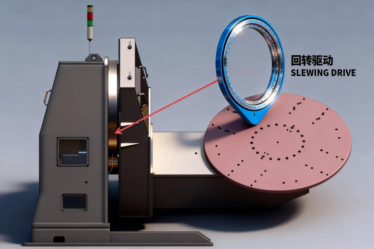
Apply documented application evidence carefully when comparing configurations
Customer cases can show that a drive type has been used in a particular application, but they do not automatically confirm suitability for another machine. Differences in loading, mounting stiffness, motor selection, environment, and duty cycle must still be checked. The useful question is not “Was this model used before?” but “Which parts of that operating condition match this equipment?”
One documented example involves a South Korean port equipment manufacturer that placed a repeat order for 20 WEA9-62-25HR single worm slew drives for port crane systems. The specified application features included self-locking behavior, IP65 sealing, and tracking precision of no more than 0.15°. This case supports the use of that identified drive configuration in its recorded port-crane conditions; it does not establish the same result for every crane or lifting system.
For marine equipment, UK Ocean Marine Systems ordered 20 units of WEA17-104-25H-R-REV.D for shipboard crane systems. A separate Newcastle, Australia marine equipment manufacturer used WEA9-61-25HR worm gear slew drives for ship deck cranes. These records show that marine crane applications require configuration attention, especially around environmental exposure and installation requirements. They do not provide a universal marine rating for every drive model.
Solar equipment presents a different set of priorities. South American solar projects in Brazil, Argentina, and Chile used SP-I 0229 spur gear slew drives for single-axis solar trackers, with recorded energy-yield improvement up to 40%. That documented outcome belongs to those projects and their tracker conditions. It should not be used as a predicted yield figure for another site without reviewing tracker geometry, control system, weather conditions, and operating strategy.
When a machine needs a different drive style, a Spur Gear Slew Drive can be discussed based on the required transmission arrangement and application layout. For machines where the rotating interface is separate from the drive assembly, the selection process may also include a Slewing Bearing review. The right architecture depends on the system layout, not on a single product preference.
Screen out unsuitable approaches before prototype release
A configured drive is not automatically the right answer for every project. If the available inputs are uncertain, a custom drawing may only lock in assumptions that later prove wrong. The design team should first separate confirmed requirements from open questions.
Common mistakes that lead to repeated interface changes
- Selecting from torque alone. Torque matters, but it does not define mounting stiffness, radial loading, tilting moment, or service clearance. Use the full load and layout data.
- Providing only a top-view drawing. A top view may hide motor height, cable exit space, guard interference, and assembly access. Provide multiple views or a 3D model when available.
- Adding adapter plates after model selection. An adapter can solve a short-term fit problem, but it may add stack height and alter the load path. Review it with the supplier before fabrication.
- Leaving cable routing until electrical commissioning. This can create inaccessible connectors or damaged cable paths. Define movement, bend space, and protection before finalizing guards.
- Assuming one case result transfers directly. A documented crane, solar, mining, or automation project can guide questions, but it cannot replace application-specific verification.
- Ignoring inspection requirements. If repeatability or positioning matters, agree on the required checks before production begins.
Quality verification should be part of the sourcing discussion. Luoyang Slewring Bearing Co., Ltd. operates an ISO 9001:2015-certified quality management system and has CE marking for the European market. Every slewing bearing passes CMM three-coordinate inspection and dynamic load testing under the company’s stated quality-control process. Buyers can also request factory audit reports when their supplier qualification process requires them.
The company has six production lines in an 8,000 m² manufacturing facility and an annual capacity of 100,000 sets. Standard production is listed at 9 days, subject to the approved configuration and production requirements. A 2-year extended quality warranty, 48-hour technical response, and free replacement for confirmed manufacturing defects provide additional support after delivery.
Use slew drive customize planning when the drive must work within fixed machine geometry and interface constraints. Use a standard model when the equipment can reasonably accommodate the existing arrangement. In either case, release the purchase order only after the mounting faces, motor arrangement, sealing requirement, cable-routing plan, and operating load conditions have been reviewed together.
For a customized layout assessment, prepare the machine drawing, load information, motor details, environmental conditions, and required production quantity. This gives Luoyang Slewring Bearing Co., Ltd. the information needed to assess a Customized Slew Drive for your equipment without relying on late-stage assumptions.
Request Your Custom Slew Drive or Bearing Spec
Tell us your load, speed, and environment — receive a tailored 100–5000 mm slewing drive or slewing bearing proposal with 3D drawings within 24 hours.
 WhatsApp

 +8613903880726