



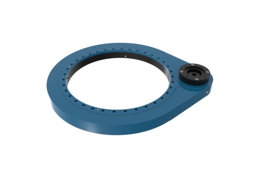
What is a worm slew drive? It is a self-contained rotation unit that combines a slewing bearing, a worm shaft, and a sealed housing in one package. The worm turns the ring gear to create rotation, and the bearing inside carries the weight and forces of whatever sits on top.
Design engineers often ask a simple question at the sizing stage. When axial, radial, and tilting loads all act at once, which part of the drive actually takes each one? The short answer is that the bearing raceway carries almost all of it, and the worm mesh is there to deliver torque. The details decide whether a drive size works or fails early.
The Bearing Carries the Load and the Worm Turns It
A slew drive has two jobs. It supports a load that rotates, and it drives that rotation. These jobs are handled by two different mechanisms inside one housing.
The slewing bearing handles the support job. Its raceways, rolling elements, and bolted rings carry the platform weight, side forces, and tilting moment. The Slew Drive adds a worm shaft and a gear on the ring so the bearing can be turned and held in position.
This split matters for early-stage selection. If you size a drive by torque alone, you may miss the moment load on the raceway. If you size by bearing rating alone, you may overload the worm mesh or the worm shaft bearings. Both checks are needed.
How Axial, Radial, and Overturning Loads Move Through the Housing, Slewing Ring, and Worm Mesh
Each load type follows a different path. The table below shows the usual path in a standard design. Exact details vary by model, so confirm them against the drawing of the drive you are considering.
| Load type | Main path through the drive | Role of the worm mesh | What it affects most |
|---|---|---|---|
| Axial (vertical weight) | Mounted structure, bolted ring, raceway rolling elements, second ring, housing bolts, base | None in the ideal case. The mesh is not a load path. | Raceway contact stress, bolt preload |
| Radial (side force) | Same ring-to-ring path, through the radially loaded part of the raceway | Small. Radial play changes tooth contact. | Raceway wear, mesh alignment |
| Overturning moment | Acts as a couple. One side of the raceway is loaded harder while the opposite side unloads. Bolts on the tension side see added stretch. | Indirect. Housing and ring deflection shift the center distance. | Peak raceway load, bolt fatigue, backlash |
| Drive torque | Motor, worm shaft, worm mesh, ring gear, rotating ring | Primary path | Tooth contact stress, worm shaft thrust bearings |
Where the worm mesh does take force
The mesh is not free of load. When it turns the ring, the tooth contact creates three force components. The main one acts along the ring tangent and delivers torque. The other two are a radial separating force and a small axial force that comes from the worm lead angle.
The worm shaft sees the reaction of those forces. Its end bearings take the thrust, which is why a drive can be strong in the raceway and still be limited by the worm shaft support. The mesh carries torque and its own reaction forces. It does not carry the weight of the machine.
Why housing stiffness matters
Under a large overturning moment, the housing and rings flex slightly. That flex can change the center distance between the worm and the ring gear. The result is uneven tooth contact, more backlash variation, and faster wear on one end of the mesh.
This is why a drive that passes a static bearing check can still wear early. The bearing may be fine, while the mesh is losing its alignment under moment load.
Parameters That Decide Combined Load Capacity
Several parameters interact. Looking at one of them alone gives a misleading answer. The table shows what each one changes in practice.
| Parameter | What it affects | Trade-off or limit |
|---|---|---|
| Raceway type and rows | Moment and axial capacity of the bearing | More rows or larger rollers add capacity but also size, weight, and cost. See Three-row Roller Slewing Bearings for the heavy end of the range. |
| Load offset (moment arm) | Overturning moment for a given weight | The same weight placed farther from the center raises the moment. Capacity charts must use the true offset. |
| Bolt count, grade, and preload | How the moment passes into the base | Weak or uneven preload causes bolt fatigue, even when the raceway is oversized. |
| Mounting surface flatness and stiffness | Raceway contact pattern | A flexible base can undo the drive's rated capacity. |
| Single or double worm | Torque capacity and mesh load sharing | A double worm design spreads torque over two meshes but adds complexity. The Double Worm Slew Drive suits higher torque demands. |
| Self-locking behavior | Holding a position without a brake in many cases | Self-locking depends on lead angle and friction. It lowers efficiency, and vibration can reduce holding ability. It is not a replacement for a brake when safety is involved. |
| Sealing and corrosion rating | Service life in dust, water, and salt | Higher protection helps life but does not raise load rating. |
Rated capacity numbers also depend on test conditions. Do not compare a static rating from one catalog to a dynamic rating from another. Ask which load case, safety factor, and duty class each number uses.
Request Your Custom Slew Drive or Bearing Spec
Tell us your load, speed, and environment — receive a tailored 100–5000 mm slewing drive or slewing bearing proposal with 3D drawings within 24 hours.
Misunderstandings That Change the Sizing Result
Three beliefs show up often in early-stage selection. Each can lead to an undersized drive.
- "The worm gear carries the load." It does not carry the platform weight. The raceway does. Sizing the worm for weight leads to the wrong parameters.
- "Self-locking means it holds any load." It means the mesh resists back-driving under normal conditions. Shock loads, wear, and vibration can change that. Add a brake when the application requires guaranteed holding.
- "A high axial rating means a high moment rating." Axial and moment capacity are separate numbers. A tall load with a short base can overturn the bearing long before its axial limit.
These points do not apply to every design. A drive with a very low moment arm, such as a flat turntable with a centered load, depends more on axial capacity and torque. A boom or tower puts the moment first.
What to request to verify a rating
- A load-moment capacity curve, not a single number.
- The assumed safety factor and duty class behind each rating.
- Bolt size, grade, count, and preload guidance.
- Backlash and tooth-contact inspection records.
- Quality records. Our Slew Drive Quality Control process includes CMM three-coordinate inspection and dynamic load testing, and our facility is ISO 9001:2015 certified.
These documents show how the unit was measured and tested. They do not replace a check against your own load case, which only you can supply.
A Worked Example and Real Applications
Here is a simple illustration, not a customer result. Assume a platform load of 10 kN sits 2 m from the rotation axis. The overturning moment is 10 kN × 2 m = 20 kN·m. If you size only on the 10 kN axial weight, you ignore the larger design driver.
Now add a wind or work force at height, such as 1 kN at 3 m above the bearing. That adds 3 kN·m and a radial force of 1 kN. The combined case is moment, axial, and radial together, which is the case a capacity curve must cover.
Real projects show how this plays out by application:
- Port cranes: A South Korean port equipment manufacturer placed a repeat order of 20 WEA9-62-25HR single worm drives. The application called for tracking precision of 0.15° or better, IP65 sealing, and self-locking.
- Slewing platforms: A Houston, Texas engineering machinery manufacturer ordered 100 units of SEA21-125-25HR(2) for slewing platform and turntable systems.
- Forestry machines: A British Columbia forestry equipment manufacturer ordered 30 units of WED14-86-25BHR.5 double worm drives for grapple machines, with precision of 0.13° or better.
Each of these has a different load mix. Cranes and grapples carry strong moments from a boom. A platform may carry mostly axial weight with a moderate offset. We cite these to show the range of use, not to claim that one model fits every case.
Checklist Before You Choose a Drive Size
Gather these inputs first. With them, a supplier can check the bearing, the mesh, and the mounting together instead of one at a time.
- Maximum axial load, including dynamic factors.
- Radial load and its direction.
- Load weight and its offset from the axis, so the moment can be calculated.
- Required torque, speed, and duty cycle.
- Holding requirement, and whether a brake is planned.
- Precision and backlash target.
- Environment, including dust, water, salt, and temperature range.
- Mounting structure stiffness and bolt pattern.
For standard sizes, a Worm Gear Slew Drive may fit your load case. If the load case or interface is unusual, a Customized Slew Drive can be matched to it. Luoyang Slewring Bearing Co., Ltd. offers a minimum order of 1 set for standard products and 5 sets for customized ones.
Send your load data and we will return a technical proposal within 24 hours. Our engineers respond to technical questions within 48 hours, and our products carry a 2-year extended quality warranty.
Request Your Custom Slew Drive or Bearing Spec
Tell us your load, speed, and environment — receive a tailored 100–5000 mm slewing drive or slewing bearing proposal with 3D drawings within 24 hours.
 WhatsApp

 +8613903880726