



What is a slew drive? It is a compact rotary actuator that combines a slewing bearing, a gear set (usually worm or spur), a housing, and a motor interface in one unit. It carries axial, radial, and tilting loads while it turns. With a precision slew drive for automation, the real question is not how fine the encoder is. It is where the encoder sits relative to the load, and how much motion hides between the two.
Here is the short answer. Indexing error shrinks when feedback sees as much of the drivetrain as possible, when resolution is comfortably finer than your tolerance, and when the gear ratio keeps each motor step small without making the axis too slow. Each choice trades against the others, so none works alone.
Where Indexing Error Comes From in a Rotary Axis
Indexing error is the gap between the commanded angle and the actual load angle after the axis stops. Automation axis repeatability is a related but different idea. It describes how closely the axis returns to the same angle over many cycles. A fixture can be repeatable yet inaccurate, and that distinction changes how you troubleshoot.
In a slew drive axis, the error builds up along a chain:
- Encoder quantization: the smallest step the feedback device can report.
- Backlash: free movement in the gear mesh when direction changes.
- Windup: elastic twist in couplings, shafts, and gear teeth under torque or inertia.
- Transmission error: small angular deviations from tooth form, pitch, and mounting.
- Structural tilt: deflection in the bearing and mounting surface under moment load.
- Control behavior: following error, overshoot, and settling time at the stop.
A common misreading is to treat the encoder datasheet as the axis specification. A high-resolution encoder on the motor shaft says nothing about backlash or windup downstream. I have seen designs with excellent feedback fail a repeatability audit because the gap sat after the sensor.
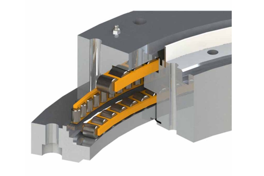
How Encoder Placement, Feedback Resolution, and Gear Ratio Tuning Reduce Indexing Error During Automated Stop-and-Position Cycles
These three parameters interact. Changing one without checking the others often moves the problem instead of removing it. The table separates what each one controls and where it stops helping.
| Parameter | What it controls | How it interacts | Trade-off or limit |
|---|---|---|---|
| Motor-side encoder | Motor shaft angle. Its step is divided by the gear ratio at the output. | Works well with a stiff, low-backlash gear stage. | Blind to backlash, windup, and tilt after the sensor. |
| Output-side encoder | Actual load angle, with gear error inside the loop. | Corrects what the motor-side sensor cannot see. | Backlash inside the loop can cause hunting. It also needs a mounting and sealing plan. |
| Dual feedback (both) | Fast inner loop on the motor, position truth at the load. | Output sensor trims the final position, motor sensor stabilizes motion. | More tuning effort and more wiring and interface work. |
| Feedback resolution | Smallest reportable angle step. | Must be finer than the error from backlash and windup to matter. | Beyond that point, finer counts add cost and noise sensitivity, not accuracy. |
| Gear ratio | Output step size, reflected inertia, and output speed. | Higher ratio gives finer steps and eases load inertia on the motor. | Lower output speed, and for worm gearing lower efficiency and more heat. It does not remove backlash. |
Placement decides what the controller can correct
A motor-side encoder is simple and common. It performs best when the load is steady and the gear stage is stiff. If your stops must hold a tolerance under changing load direction, the sensor needs to see the output.
An output-side encoder closes the loop around the whole drivetrain. That includes backlash, so the controller may reverse a few times near the target. Moderate gains, a final approach from one direction, or dual feedback usually tame this. This is the main reason slew drive encoder integration should be planned before the housing and motor interface are frozen.
Resolution only matters up to the largest other error
Here is a hypothetical calculation, not a product specification. Suppose a motor encoder gives 10,000 counts per revolution and the ratio is 50:1. The output sees 500,000 counts per turn, or about 0.00072° per count. If the gear mesh has 0.1° of lash, the count size is irrelevant at the stop.
So how do you reduce rotary indexing error in practice? Find the largest term in the chain first. Then choose resolution several times finer than your tolerance and spend the rest of the budget on stiffness, backlash control, and output feedback.
Ratio tuning for stop-and-position cycles
A higher ratio divides the load inertia seen by the motor by the ratio squared. That helps settling at the stop. But the motor must spin faster to hit the same cycle time, and worm stages run warmer at high ratios. Check the cycle time and duty cycle together before you pick the ratio.
Limit: if your axis rarely reverses and always approaches from the same side, backlash matters less. Then a motor-side encoder and a well-chosen ratio may be enough.
Request Your Custom Slew Drive or Bearing Spec
Tell us your load, speed, and environment — receive a tailored 100–5000 mm slewing drive or slewing bearing proposal with 3D drawings within 24 hours.
Choosing the Gear Type Before Choosing the Encoder
Gearing sets the error floor that feedback has to work with. Luoyang Slewing Bearing Co., Ltd. builds each of the following types. The cases below show how the drives were specified in real applications, not encoder results.
| Drive type | Position holding | Case from our files | Indexing consideration |
|---|---|---|---|
| Worm Gear Slew Drive | Self-locking in the cases below | South Korean port equipment maker: 20 units of WEA9-62-25HR for port cranes, ≤0.15° tracking precision, IP65 sealed | Holds position unpowered, but backlash still exists and an output encoder can see it. |
| Double Worm Slew Drive | Self-locking worm gearing | British Columbia forestry equipment maker: 30 units of WED14-86-25BHR.5 for grapple machines, ≤0.13° precision | Chosen where a tighter precision target applied. Confirm precision grade and backlash on your own drawing. |
| Spur Gear Slew Drive | Generally needs a brake or holding torque | Manchester, UK automation equipment maker: 100 units of SP-I 0841-32.1 for automated turntables | Higher mechanical efficiency typically means a brake in the stop-and-hold cycle. |
Worm drives hold position without power, which suits cranes and handling gear that must not creep. Spur drives suit continuous or frequently cycling turntables where efficiency matters. Neither is automatically more precise, because the error chain includes mounting and control too.
Our SE and WE series follow German-standard designs and are localized with P0 to P4 precision grades. Ask which grade your tolerance assumes before you compare quotes. A higher grade is not always the right grade if your load and mounting cannot support it.
Common Mistakes When Specifying an Encoder Slew Drive
- Buying resolution to fix a backlash problem. Finer counts do not close mechanical lash. Measure lash at the output first.
- Using accuracy and repeatability as one number. Ask which one a tolerance refers to, and under what load.
- Ignoring mounting surface flatness. A bearing mounted on a warped plate adds tilt and transmission error that no sensor can remove.
- Setting high gains with an output encoder. Backlash inside the loop turns aggressive tuning into hunting at the stop.
- Comparing precision figures taken under different conditions. A no-load figure and a loaded, direction-reversing figure are not equivalent.
- Freezing the housing before the encoder is chosen. Late encoder mounting forces compromises in alignment and sealing.
What to inspect and what the evidence tells you
Ask for dimensional inspection records on the gear and raceway parts. Every slew bearing we produce passes CMM three-coordinate inspection and dynamic load testing. Our Slew Drive Quality Control page explains the process, and our factory operates under ISO 9001:2015. These records show part consistency. They do not replace a test of your complete axis with your motor, load, and controller.
A Worked Scenario for a Rotary Indexing Fixture
Consider a hypothetical fixture that must index to ±0.1° under a changing tool load. The team measures stops with a motor-side encoder and finds scatter that does not match the counts. The usual cause is lash and windup after the sensor, so the fix is feedback location, not a finer encoder.
Work through it in this order:
- Measure output angle with an external reference at ten stops from each direction.
- Compare results by approach direction. A directional offset points to backlash or windup.
- Add or relocate feedback at the output, or adopt a one-direction final approach.
- Recheck the gear ratio against inertia and cycle time.
- Test again under the real tool load, not only at no load.
For the base unit, a standard Slew Drive often meets the need. If your encoder type, mounting envelope, or motor interface is unusual, a Customized Slew Drive avoids adapter plates that add their own compliance.

Checklist Before You Finalize the Motion Architecture
Gather these items before you request a quotation. Missing data is the most common reason a first proposal needs revision.
- Required tolerance, and whether it means accuracy or repeatability.
- Load profile: axial, radial, and tilting moment, plus inertia and duty cycle.
- Cycle time and stop frequency, with direction reversals noted.
- Encoder type, resolution, interface, and preferred location.
- Holding method: self-locking worm or brake.
- Environment: dust, washdown, or outdoor exposure. Our slew drives offer protection up to IP66.
- Quantity: standard units start at 1 set, customized units at 5 sets.
Luoyang Slewing Bearing Co., Ltd. has focused on slew bearing and slew drive R&D for over 15 years across more than 2,000 heavy-equipment projects. We return a technical proposal within 24 hours, and rapid prototyping takes 3 days. Confirmed manufacturing defects are replaced free under our 2-year extended quality warranty, and technical questions get a response within 48 hours.
Those terms apply to our standard process. Your actual lead time, precision grade, and encoder arrangement depend on the drawing and the load case you send.
Request Your Custom Slew Drive or Bearing Spec
Tell us your load, speed, and environment — receive a tailored 100–5000 mm slewing drive or slewing bearing proposal with 3D drawings within 24 hours.
 WhatsApp

 +8613903880726