



What is a slew drive? A slew drive is a compact rotary unit that combines a slewing bearing, gear system, housing, and mounting interface to rotate or hold a machine structure under load. It is commonly used in solar trackers, cranes, aerial platforms, excavators, turntables, and automation equipment.
The decision is rarely about selecting the largest unit. Engineers must balance axial load, radial load, overturning moment, rotation speed, operating frequency, environmental exposure, and installation space. Knowing how to choose slew drive capacity early helps prevent expensive redesigns after the motor, frame, and rotating equipment have already been specified.
For equipment designers, the best selection process starts with machine forces rather than product size. A compact drive may fit the frame but fail to meet moment demand, while an oversized model can add unnecessary weight, cost, and motor requirements. Luoyang Slewring Bearing Co., Ltd. supports early-stage selection with technical proposals available within 24 hours when the application inputs are complete.
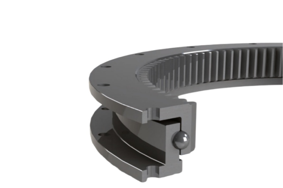
Start with the machine conditions instead of the drive model
A slew drive should be selected from the loads it will see at the rotation center. The four inputs that matter most are axial load, radial load, overturning moment, and duty cycle. These values work together, so reviewing only one load type can lead to an unsuitable selection.
Axial load acts parallel to the rotation axis. It often comes from the weight of a platform, solar structure, boom assembly, tool, or payload. This load is usually present even when the machine is stationary, so it must be evaluated in both parked and operating positions.
Radial load acts perpendicular to the rotation axis. It can come from side loading, wind, offset-mounted equipment, uneven material handling, or forces created during motion. A machine with low vertical weight can still have meaningful radial demand if the rotating structure experiences side force.
Overturning moment is often the deciding load. It occurs when a force acts at a distance from the slew center, such as a crane boom carrying material away from the mounting plane. The basic relationship is simple: force multiplied by distance creates moment. A small load placed far from the center can therefore create a large demand on the drive.
| Input to Collect | What It Represents | Typical Source | Why It Changes Selection |
|---|---|---|---|
| Axial load | Load parallel to the rotation axis | Platform weight, payload, rotating structure weight | Sets the vertical support demand on the bearing system |
| Radial load | Side force across the rotation axis | Wind, boom force, material contact, side pull | Can affect bearing loading and housing support needs |
| Overturning moment | Tipping force around the mounting plane | Offset payloads, long booms, elevated structures | Often controls the required drive size and mounting layout |
| Duty cycle | How often and how long the drive operates | Intermittent movement, repeated tracking, frequent indexing | Changes heat, wear, lubrication, and gear loading conditions |
| Rotation speed | Required output rotation rate | Tracker movement, crane positioning, turntable indexing | Influences gear ratio and motor matching |
| Environment | Exposure around the drive | Dust, salt spray, rain, heat, cold, corrosion | Determines sealing and corrosion-protection requirements |
Use maximum expected working loads, not only nominal weights. A designer should also identify loads during starting, stopping, transport, wind exposure, tool contact, and off-center loading. If those conditions are unknown, the correct next step is to identify them before requesting a final rating confirmation.
For very high load applications, a separate bearing arrangement may be more suitable than an integrated drive. In that situation, review options such as a Heavy load slewing bearing alongside the drive concept. This approach can fit machines where the bearing must carry exceptional structural loads while another drivetrain provides rotation.
Translate axial, radial, moment, and duty inputs into a selection envelope
A useful slew-drive selection envelope is the range of conditions the unit must support at the same time. It is not a single axial-load figure or a single torque target. The envelope combines load direction, load location, operating duration, speed, holding needs, mounting stiffness, and exposure conditions.
Build the envelope before comparing catalog sizes. The result gives a supplier enough information to screen standard models, identify missing data, or recommend a Customized Slew Drive when a standard arrangement does not match the machine.
| Selection Step | Input to Provide | Selection Meaning | Best Fit | Boundary to Check |
|---|---|---|---|---|
| 1. Define the static condition | Dead weight, payload, center of gravity, mounting orientation | Establishes the standing axial and moment demand | All rotating equipment | Do not assume the center of gravity stays fixed during operation |
| 2. Define operating forces | Side forces, wind effects, tool forces, boom loads, acceleration effects | Adds radial and dynamic moment demand | Cranes, excavators, forestry tools, platforms | Unknown external forces must be confirmed before final selection |
| 3. Define motion demand | Rotation angle, output speed, starts, stops, direction changes | Supports motor and gear arrangement review | Turntables, trackers, steering systems | High-frequency reversing needs a duty review, not only torque review |
| 4. Define duty cycle | Run time, rest time, daily operating pattern, parking time | Shows whether heat and repeated loading need added attention | Continuous or repetitive machines | Short intermittent duty cannot represent repeated production operation |
| 5. Define the environment | Dust, water, salt exposure, corrosion risk, temperature conditions | Sets sealing and surface-protection requirements | Outdoor, marine, mining, desert equipment | Protection rating must match actual installation exposure |
| 6. Confirm installation | Mounting plate layout, fasteners, flatness, available envelope | Verifies that the machine structure can support the selected unit | All applications | A capable drive cannot compensate for a weak or distorted mounting structure |
For a low-speed solar tracker, the selection envelope may include a relatively stable structure load, repeated small-angle movement, outdoor sealing requirements, and long periods holding position. For a crane or forestry grapple, the envelope may include changing offset loads, more demanding overturning moment, shock-related operating events, and frequent directional changes.
The conclusion is practical: use a standard drive when the calculated envelope fits verified catalog ratings and available mounting space. Move to a custom design when the interface, load direction, gear arrangement, sealing requirement, or operating pattern falls outside the standard product configuration. Do not treat a size name alone as a load rating.
Match the drive arrangement to the operating case
After defining the selection envelope, compare the gearbox arrangement to the machine’s motion and holding requirements. The choice between worm gear, double worm, and spur gear systems should follow the application, not a general assumption that one arrangement is always better.
Use a single worm arrangement for controlled rotation and holding-oriented applications
A Worm Gear Slew Drive is commonly considered where compact rotary motion and controlled positioning are required. It can suit tracker systems, deck cranes, truck-mounted cranes, and rotating platforms when the verified load envelope fits the supplier’s approved rating.
The limitation is that the exact holding performance, torque requirement, and duty suitability must be checked for the selected configuration. Do not assume every worm-drive arrangement provides the same self-locking behavior under every load direction, lubrication condition, or operating pattern.
Consider double worm designs when load sharing and higher stability are needed
A Double Worm Slew Drive can be considered when a machine needs greater rotational stability or a more demanding load case than a comparable single-worm arrangement can support. This may suit heavy wheel steering, mining equipment, and forestry machinery with repeated offset forces.
A documented example comes from British Columbia, Canada, where a forestry equipment manufacturer ordered 30 WED14-86-25BHR.5 double worm slew drives for forestry grapple machines. The stated application required precision of no more than 0.13 degrees. That case supports the suitability of the specified model for that customer’s equipment, but it does not establish the same result for another grapple design with different loads, mounting stiffness, or duty conditions.
Use spur gear drives for suitable low-speed tracking or indexed rotation duties
A Spur Gear Slew Drive can fit applications where the machine layout and required motion suit a spur gear arrangement. It is often considered for solar tracking and automated turntable systems, subject to verified load and environmental requirements.
For example, South American solar projects in Brazil, Argentina, and Chile used SP-I 0229 spur gear slew drives for single-axis solar trackers. The recorded project result was an energy-yield increase of up to 40%. That result belongs to those project conditions; site layout, tracker controls, panel configuration, weather, and existing system design must all be reviewed before using that figure in another project forecast.
Request Your Custom Slew Drive or Bearing Spec
Tell us your load, speed, and environment — receive a tailored 100–5000 mm slewing drive or slewing bearing proposal with 3D drawings within 24 hours.
Evaluate duty cycle before choosing motor size and gear capacity
Duty cycle describes how long the drive runs, rests, reverses, and holds position. Two machines can have the same maximum load but require different slew drives because one moves occasionally while the other repeats rotation throughout the workday.
For intermittent duty, record the rotation angle, the number of starts and stops, the length of each motion period, and the time between movements. This is common in truck cranes, lifting platforms, and service equipment. The main concern is whether peak loads occur during starts, braking, or off-center lifting events.
For repetitive duty, document the full cycle rather than only the peak load. Automated turntables, production fixtures, and steering equipment may repeatedly accelerate, stop, and reverse. These conditions should be presented to the supplier because repeated loading changes the design review for gears, bearing raceways, lubrication, and motor matching.
For tracking duty, the drive may rotate slowly in small increments and remain parked for long periods. In this case, holding behavior, environmental sealing, and long-term exposure can matter as much as output speed. The U.S. renewable energy equipment manufacturer that ordered 50 SP-I 0841 units for utility-scale solar tracker systems specified IP65 protection for desert sites, showing how location exposure can become a defined purchasing requirement.
- Choose by peak load only when the operation is truly infrequent and dynamic conditions are limited. This does not apply to repetitive production equipment or frequent reversing duty.
- Choose by the full cycle profile when the machine starts, stops, reverses, or runs repeatedly. Include operating hours and rest periods in the specification request.
- Specify holding conditions separately when the machine must remain fixed under wind, suspended loads, or parked structure loads. Rotation torque alone does not describe this condition.
- Review environmental exposure with duty when the equipment works outdoors or near corrosive media. A drive protected during brief motion can still face exposure while parked.
Luoyang Slewring Bearing Co., Ltd. offers slew-drive protection up to IP66 and anti-corrosion protection up to C4H, depending on the configuration and application requirement. These options should be selected against the real installation environment rather than added automatically to every design.
Use application evidence correctly when comparing options
Customer cases are useful when the machine conditions are close to your own. They are not substitutes for load calculations or rating verification. Compare the application type, load direction, duty cycle, environment, precision need, and mounting arrangement before transferring a prior selection to a new machine.
| Recorded Application | Selected Product | Known Requirement or Result | What Another Buyer Must Still Verify |
|---|---|---|---|
| South Korean port crane systems | WEA9-62-25HR single worm slew drives | 20-unit repeat order; no more than 0.15 degree tracking precision; IP65 sealed; self-locking | Crane geometry, load chart, duty pattern, mounting structure, motor arrangement |
| Australian mining excavators | HWE21-94-25HR.1 double worm slew drives | Used for mining excavator applications | Excavator working loads, shock conditions, attachment forces, installation envelope |
| Houston heavy-duty wheel steering systems | WED17-104-25HR double worm slew drives | 150 units ordered for heavy-duty wheel steering | Steering angle, cycle frequency, tire forces, duty cycle, control system |
| Manchester automated turntables | SP-I 0841-32.1 | 100 units ordered for automated turntable systems | Table mass, center-of-gravity location, indexing frequency, motor sizing |
For port and marine equipment, corrosion exposure and sealing must be assessed alongside load capacity. UK Ocean Marine Systems ordered 20 WEA17-104-25H-R-REV.D units for shipboard crane systems, while a Newcastle, Australia manufacturer used WEA9-61-25HR worm gear slew drives for ship deck cranes. These are relevant reference points for marine buyers, but neither order defines a universal marine specification.
Quality verification should also be part of the commercial comparison. Our ISO 9001:2015-certified facility uses CMM three-coordinate inspection and dynamic load testing for every slewing bearing. Luoyang Slewring Bearing Co., Ltd. also provides a 2-year extended quality warranty and free replacement for confirmed manufacturing defects, which can help purchasing teams define supplier-evaluation requirements beyond the initial unit price.
Prepare a request for quotation that supports a usable recommendation
A supplier can give a faster and more useful proposal when the request includes the actual machine inputs. A product photo and a desired outer diameter are not enough for a reliable recommendation. Provide the information below, then ask the supplier to identify any missing conditions before confirming a model.
- Describe the machine: State whether it is a crane, solar tracker, excavator, turntable, platform, steering system, or another rotating assembly.
- Provide loads at the rotation center: Include axial load, radial load, overturning moment, payload position, and center-of-gravity location for relevant operating positions.
- Define the duty cycle: List rotation angle, output speed, starts and stops, direction changes, run time, rest time, and expected operating schedule.
- State holding needs: Explain whether the drive must hold a parked structure, resist wind-related movement, or maintain position under external load.
- Share environmental conditions: Identify dust, water, salt exposure, temperature conditions, corrosion risk, and required protection level.
- Confirm the mounting interface: Provide drawings or dimensions for the mounting plate, bolt layout, available installation space, and motor position.
- State commercial needs: Include quantity, target schedule, sample requirement, and whether a standard or customized solution is acceptable.
Standard product orders can start from one set, while customized products have a minimum order quantity of five sets. Sample orders are welcome for testing and evaluation. The company operates six production lines in an 8,000 m² facility with annual capacity of 100,000 sets, and standard production is listed at nine days after requirements are confirmed.
Use the selection envelope as the decision record for your engineering and purchasing teams. It makes it easier to compare a standard Slew Drive against a custom option, identify what must be verified, and avoid selecting solely by product dimensions or initial price.
When comparing quotes, ask each supplier to confirm the load conditions reviewed, duty assumptions, environmental protection level, included motor interface, inspection process, warranty terms, and exclusions. This creates a clear technical basis for the purchase decision and reduces the risk of receiving a drive that fits physically but does not match the application.
Request Your Custom Slew Drive or Bearing Spec
Tell us your load, speed, and environment — receive a tailored 100–5000 mm slewing drive or slewing bearing proposal with 3D drawings within 24 hours.
 WhatsApp

 +8613903880726