



What is a slew bearing drawing? It is the controlled engineering document that defines the bearing envelope, mounting-hole pattern, gear position when applicable, load direction references, and other details needed to connect a slewing ring to a machine structure.
For engineers reviewing an existing flange, adapter, or fixture, the main question is simple: can the holes on the machine interface physically align with the bearing and accept the specified fasteners? A slew bearing drawing answers that question only when its hole callouts, reference views, and revision status are read together.
A matching outside diameter is not enough. Two rings can have the same general envelope but use different bolt-circle diameters, hole quantities, hole types, thread engagement requirements, or angular positions. If any of those items differ, the bearing may arrive on site and still be impossible to mount.
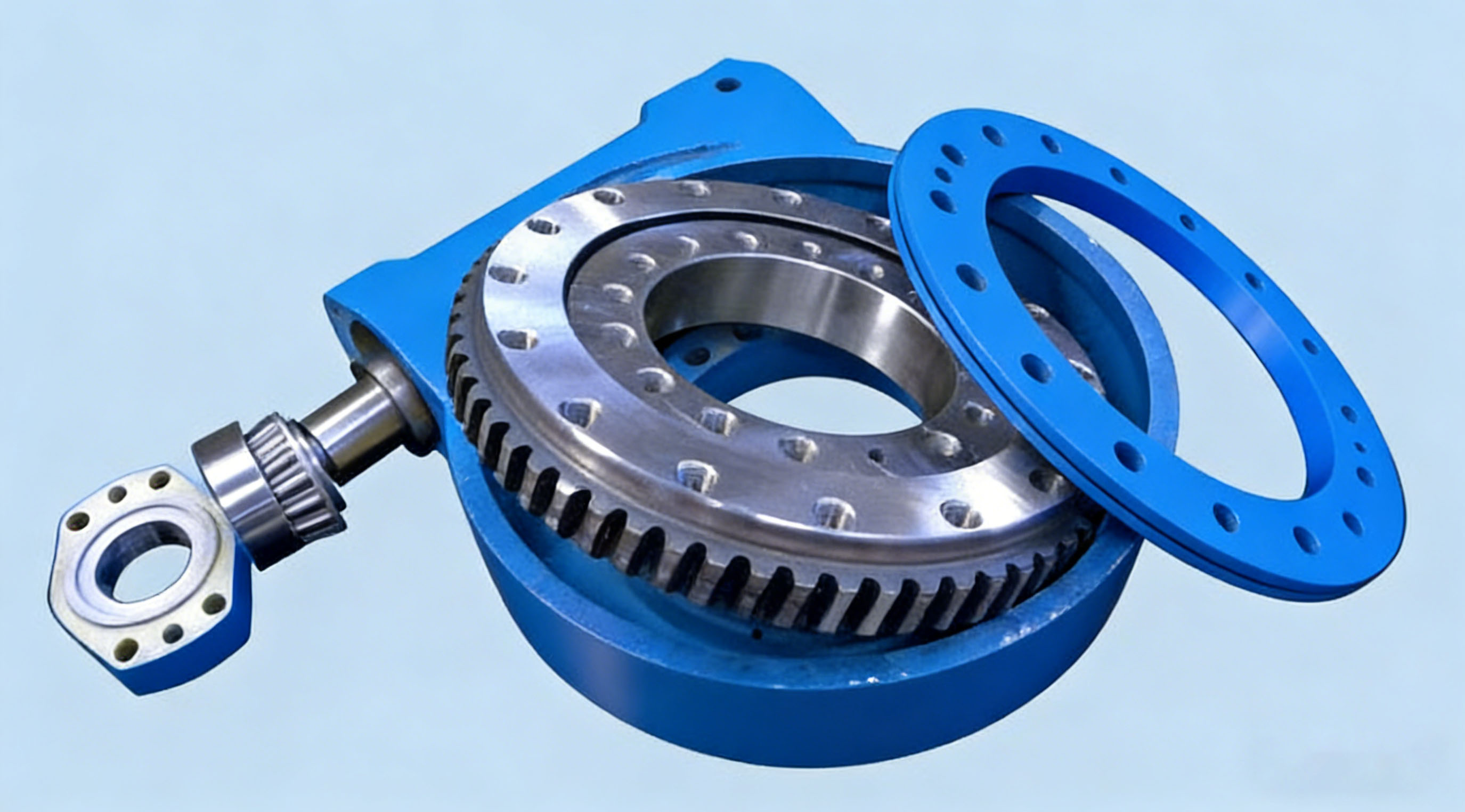
Start With the Mounting Interface Rather Than the Bearing Outside Diameter
The first action is to separate “will it fit inside the space?” from “can it be bolted to the machine?” Outside diameter, bore diameter, and height determine envelope compatibility. Mounting-hole data determines whether the bearing can be installed without changing the flange, bolt selection, or assembly method.
For a bearing replacement, compare the existing machine drawing against the bearing document line by line. Do not rely only on a previous part number, a supplier photograph, or a verbal description such as “same size ring.” The actual part may have been modified across revisions, especially where a customer-specific interface was used.
| Drawing Item | What It Defines | Practical Effect | When It Is Not Enough Alone |
|---|---|---|---|
| Outside diameter | Maximum radial envelope | Shows whether the ring can sit within the surrounding structure. | It does not prove that mounting holes align. |
| Inside diameter | Clearance through the center opening | Checks interference with columns, cables, hydraulic lines, or center shafts. | It does not confirm bolt access or fastener engagement. |
| Bolt-circle diameter | Diameter through the centers of a hole group | Sets the radial location of every mounting hole. | It must be checked with hole count and angular clocking. |
| Hole callout | Threaded, through, counterbored, or other hole form | Determines which side receives the bolt and how the joint is assembled. | It must be checked with thread depth and available flange thickness. |
| Reference feature | Start point for angular location | Shows where a hole pattern begins relative to a marked feature. | It must match the machine datum and any required orientation. |
Use the bearing center axis as the primary reference unless the drawing states another datum. Then identify the inner-ring and outer-ring mounting patterns separately. A common error is to check only one ring because the drawing view appears symmetric, while the machine needs both rings to mate with different structures.
For applications where the bearing carries an external gear or internal gear, also identify the gear location and mesh side. The mounting pattern may fit, but the bearing can still be unusable if the pinion is located on the opposite side of the machine from the gear.
Luoyang Slewring Bearing Co., Ltd. supplies Slewing Bearing products for equipment interfaces that need this type of drawing review. For high-load arrangements, the bearing design itself also affects the flange concept; compare the product layout with the requirements of a Heavy load slewing bearing before releasing the steelwork.
When Bolt-Circle Details Create an Unbuildable Mounting Interface
A mounting interface becomes unbuildable when the flange and bearing cannot be assembled using the specified holes and fasteners without rework. The four details that most often cause this result are bolt-circle diameter, hole type, thread depth, and clocking. They interact, so none should be approved in isolation.
| Parameter | What to Read on the Drawing | How It Interacts With Other Details | What Changes in Practice if It Is Wrong |
|---|---|---|---|
| Bolt-circle diameter | The circle diameter passing through hole centers for the inner or outer ring. | It must match the flange drilling radius and the intended bearing ring. | Bolts do not enter the holes, even if the same number of holes is present. |
| Hole type | Whether holes are tapped, through holes, or include a seat feature. | It determines bolt direction, washer or head clearance, and whether a nut is needed. | A bolt may bottom out, lack access for a nut, or have no proper seating surface. |
| Thread depth | The usable depth of a tapped hole, not only the thread designation. | It must suit the bolt length after flange thickness, washers, and any spacer are included. | The bolt can bottom before clamping, or engagement may be too limited for the joint design. |
| Clocking details | The angular start location, unequal spacing, blank sectors, or reference-hole position. | It must align with the machine datum, gear side, lubrication access, and nearby components. | One or more holes miss, or the ring installs in a position that blocks service access. |
Conclusion: treat the bolt circle as a coordinate system, not as a single diameter. This approach fits every replacement project and every new flange design. It does not replace a structural joint calculation, but it prevents a basic geometry failure before that calculation begins.
For example, a flange may have the correct number of holes on the correct nominal circle. If the bearing pattern starts from a different angular reference, the first few holes may look nearly aligned but the mismatch becomes visible around the ring. That is clocking failure, not a minor machining variation.
Hole type creates a second boundary. A tapped bearing ring generally requires the bolt to enter from the mating structure side. A through-hole ring may require the bolt to pass through and be secured from the opposite side. These arrangements cannot be treated as interchangeable because the available assembly access, flange thickness, and bolt-head clearance may be completely different.
Thread depth creates a third boundary. A longer bolt is not automatically safer. If it reaches the bottom of a blind threaded hole before the flange is clamped, the assembly can appear tightened while the joint has not developed the intended clamping force. Conversely, a short bolt may not provide the engagement required by the fastening design.
Clocking matters most when the drawing shows a reference mark, grease fitting, plug, gear gap, blank hole sector, or unequal pattern. In that case, do not assume rotational symmetry. Ask for the angular location from a defined datum and transfer that datum to the flange drawing.
Use this boundary test before flange machining
- Reject the interface for review if the bearing and flange use different bolt-circle diameters for the mating ring.
- Reject the interface for review if one document shows threaded holes and the other assumes through-bolts with nuts.
- Reject the interface for review if the selected bolt cannot be checked against the stated usable thread depth.
- Reject the interface for review if the drawing has a reference feature but the flange pattern has no matching angular datum.
- Request clarification if a hole pattern is described only as “equally spaced” but the drawing also shows service components that may require orientation.
This check is especially useful before machining a welded turntable or drilling a costly adapter plate. It may not identify every concern, such as flange flatness or local structural deflection, but it identifies the conditions that make correct assembly impossible from the start.
Request Your Custom Slew Drive or Bearing Spec
Tell us your load, speed, and environment — receive a tailored 100–5000 mm slewing drive or slewing bearing proposal with 3D drawings within 24 hours.
Read Hole Callouts as Assembly Instructions
A drawing callout is more than a manufacturing note. It tells the design team how the bearing joint will be assembled, inspected, and serviced. Read each mounting-hole note together with the cross-section view, because the top view often cannot show blind-hole depth, counterbore form, or bolt entry direction.
Begin by identifying whether the hole is located in the inner ring or outer ring. Then trace which machine component mates with that ring. In a turntable, one ring may bolt to the stationary base while the other connects to the rotating upper structure. Reversing that assumption can lead to a flange design that is physically correct on paper but installed on the wrong component.
- Confirm the drawing revision, part number, and any customer-specific suffix.
- Mark the bearing center axis and the mounting face used by each ring.
- Record the hole count, bolt-circle diameter, hole type, and spacing method for each ring.
- Find the angular datum, reference hole, plug, grease point, or gear-related feature that controls orientation.
- Compare the flange hole coordinates against the bearing pattern from the same datum.
- Check the proposed fastener stack, including flange thickness, washers, spacers, and the stated thread depth.
- Confirm tool access for tightening and later maintenance.
- Hold fixture release until drawing discrepancies are resolved in writing.
Use a coordinate table when the pattern is not fully uniform. List each hole by radius and angle from the same zero point. This is clearer than comparing visual positions from two separate drawing sheets, and it gives the machinist a direct inspection reference.
Do not treat a general arrangement drawing as the final authority for production drilling. General arrangements can help with envelope checks, but the controlled approval drawing should define the mounting interface. If the supplier provides a revision update, repeat the comparison even where the overall dimensions look unchanged.

Prevent Common Drawing Review Errors Before Fixture Release
The most expensive mistakes happen when a correct dimension is applied to the wrong ring, wrong face, or wrong reference. These errors are preventable when the reviewer records what each dimension controls rather than copying values into a CAD model without context.
- Using the outside diameter as the drilling reference: This may work only by coincidence. Use the bearing center and the specified bolt circle instead.
- Counting holes without checking spacing: Equal hole quantity does not prove equal angular spacing or the same starting position. Check the pattern note and the reference feature.
- Assuming all threaded holes are through threads: A blind thread requires depth verification and can limit bolt length.
- Ignoring the assembly side: A drawing may show the same pattern in plan view while the cross-section reveals that fasteners must enter from a specific side.
- Omitting wrench access: A bolt pattern can align but remain difficult to assemble if nearby ribs, guards, gear housings, or hydraulic fittings block tools.
- Modeling from an outdated PDF: Always confirm the revision identifier before using dimensions for fixture or flange release.
- Forgetting gear and service orientation: The holes may align while the pinion, grease point, or inspection location faces an inaccessible direction.
Recommendation: use a drawing review sheet that requires a signoff for each mounting ring. This fits projects with multiple reviewers, outsourced machining, or existing equipment interfaces. It is less necessary for a simple internal prototype where the same engineer owns the bearing, flange, and fixture models, but even then a second check is valuable before material is cut.
At Luoyang Slewring Bearing Co., Ltd., our engineering and manufacturing work includes drawing support for standard and custom arrangements. Our facility is ISO 9001:2015 certified, and our quality process includes CMM three-coordinate inspection and dynamic load testing for each slewing bearing. Those controls help verify manufactured geometry, but the customer machine interface still needs to be confirmed during design review.
Match the Drawing Review to the Bearing and Drive Application
The importance of bolt-pattern verification changes with the equipment layout. A light rotating display may allow a simple adapter redesign. A crane, excavator, marine platform, solar tracker, or automated turntable can involve more restricted space, gear location constraints, and costly downtime if the mounting interface is wrong.
For a direct slewing ring installation, review both mating structures and the ring orientation. Product families such as Single Row Slewing Ring Ball Bearings may suit applications where the ring is integrated into the machine structure, but the mounting holes still must match the base and rotating frame drawings.
For a self-contained drive, the interface review changes. A Slew Drive adds housing mounting points, output connection features, motor orientation, and protection needs to the bearing-related checks. The bolt pattern is still important, but it is now only one part of the full equipment interface.
Consider a machine builder replacing an existing rotating platform bearing. The team finds a ring with a similar envelope and matching hole count. Before proceeding, it should compare both bolt circles, identify which ring bolts to the base, verify the hole type on each side, and confirm where the gear or lubrication point must face. If the old flange was drilled from a different angular datum, an adapter may be required instead of a direct replacement.
A real drive application shows why application details cannot be ignored. A Houston, Texas engineering machinery manufacturer ordered 100 SEA21-125-25HR(2) units for slewing platform and turntable systems. In such systems, the equipment designer must account for the drive mounting pattern and output connection, rather than assuming that a bearing-only flange layout will transfer directly.
For equipment that cannot accept a standard mounting pattern, a Customized Slew Drive may be the better route. This is appropriate when the machine needs a specific housing interface, output form, motor position, or operating arrangement. It does not remove the need for drawing control; it makes the approved interface drawing even more important.
Send a Complete Verification Package Before Production Begins
The best purchasing request contains more than the bearing model. Send the existing machine interface drawing, the desired bearing orientation, the loading direction description, the available installation space, and any limits on bolt access or service access. This gives the bearing supplier enough information to identify visible interface conflicts before production.
Where a new flange or fixture is being designed, provide the CAD model or dimensioned drawing of the mating structure. Include the center datum, bolt-hole coordinates, intended fastener direction, and any parts that could interfere with bolt heads, nuts, tools, gears, seals, or lubrication points.
| Document or Detail to Provide | What It Allows the Supplier or Reviewer to Check | Risk if Missing |
|---|---|---|
| Current machine flange drawing | Existing bolt circle, hole pattern, face arrangement, and available space. | The proposed bearing may not mount directly. |
| Required bearing orientation | Gear side, grease access, plug location, and ring assignment. | The part may fit but face the wrong direction. |
| Fastener concept | Entry direction, bolt length concept, and threaded-hole compatibility. | The joint may not assemble as intended. |
| Fixture or adapter drawing | Coordinate consistency between the new component and the bearing. | Machined parts may require rework or replacement. |
| Approved drawing revision | Controlled communication between buyer, designer, and manufacturer. | Different teams may build to different dimensions. |
Luoyang Slewring Bearing Co., Ltd. can provide a technical proposal within 24 hours and offers 3-day rapid prototyping for suitable projects. Standard production is listed at a 9-day cycle, while custom work should be reviewed against the actual design scope and approval status. Standard product MOQ is one set, and customized product MOQ is five sets, which can help engineering teams validate an interface before a larger equipment release.
Before approving a fixture, flange, or adapter, verify the bolt-circle diameter, hole type, thread depth, and clocking from the controlled drawing. Then check fastener access and orientation features. That short review can prevent a bearing that looks correct in a catalog from becoming an unmountable part in the workshop.
Request Your Custom Slew Drive or Bearing Spec
Tell us your load, speed, and environment — receive a tailored 100–5000 mm slewing drive or slewing bearing proposal with 3D drawings within 24 hours.
 WhatsApp

 +8613903880726