



Which ratings should an engineer trust when estimating slewing bearing service life? A slew bearing datasheet provides load capacities, dimensions, gear details, and mounting data, but no single catalog value can predict life by itself. The useful answer comes from comparing the actual axial load, radial load, tilting moment, rotation pattern, mounting stiffness, and lubrication conditions with the rating conditions used by the manufacturer.
For early design selection, start with the published axial, radial, and moment ratings. Then check whether those loads occur separately or at the same time. A bearing that looks acceptable under one load direction may have a much shorter usable life when it carries a combined load from an offset boom, rotating platform, or uneven structure.
Luoyang Slewring Bearing Co., Ltd. supplies Slewing Bearing and Slew Drive products for applications that combine heavy loads with slow rotation. Our engineering team can provide a technical proposal within twenty-four hours when the load case, mounting arrangement, duty cycle, and environmental conditions are clearly defined.

Start With the Rating Type Before Comparing Capacity Values
The first selection mistake is treating every published capacity as the same kind of rating. Datasheets may show static load capacity, dynamic capacity, allowable load combinations, gear tooth strength, bolt requirements, or application-specific limits. Each answers a different question.
Static ratings help assess whether the bearing can resist a peak or parked load without permanent raceway damage. They are most relevant to cranes holding a suspended load, work platforms parked at reach, transport loads, wind exposure, and emergency stop conditions. Static capacity alone does not prove that the bearing will last through repeated rotation cycles.
Dynamic ratings relate to repeated rolling contact under load. They matter when a bearing rotates through many cycles, even if its speed is low. A solar tracker, automated turntable, forestry grapple, or excavator may rotate slowly, yet repeated loaded movement can still govern raceway fatigue and gear wear.
Allowable load combination data is often more useful than isolated ratings. A slewing ring rarely sees only axial force or only moment. A boom-mounted load creates downward force and overturning moment together, while a drive pinion can add tangential gear force and radial load at the same time.
Use the rating that matches the failure mode being checked. Select static ratings for peak-load safety, dynamic information for repeated rolling life, gear data for transmission loading, and bolt information for joint integrity. Do not use a high static rating as proof of long fatigue life.
Ask what conditions were used to establish the rating
A capacity value has meaning only when its supporting conditions are known. Request the manufacturer’s load diagram, permissible load curve, duty-cycle assumptions, mounting requirements, and lubrication instructions. If the datasheet does not state whether ratings apply to combined loading, assume that more verification is needed.
This is especially relevant for nonstandard equipment. A bearing in a laboratory turntable may experience controlled loading and clean conditions, while the same size bearing in a mining attachment may face shock, dirt, vibration, and structure deflection. The catalog part number may be similar, but the selection result should not be assumed to be the same.
Comparison: Maps Axial, Radial, and Tilting-Moment Ratings to the Operating Conditions That Actually Determine Bearing Life
Axial, radial, and tilting-moment ratings interact because they load the same rolling elements and raceways from different directions. The highest listed number is not automatically the better choice. The better bearing is the one whose combined-load capability fits the real duty cycle and mounting structure.
| Datasheet rating | What it represents | Operating condition that drives it | Effect on service life | Where it does not provide enough information |
|---|---|---|---|---|
| Axial load rating | Capacity for force acting parallel to the bearing axis. | Vertical payload, dead weight, suspended equipment, platform weight, and downward process force. | High axial force increases contact stress between rolling elements and raceways. Repeated axial loading can shorten rolling-contact life. | It cannot represent an offset load by itself. A load acting away from the bearing center also creates tilting moment. |
| Radial load rating | Capacity for force acting perpendicular to the bearing axis. | Side loading from booms, eccentric equipment, chain pull, gear mesh force, acceleration, or side wind. | Radial force can shift raceway contact and add stress to rolling elements. It may also affect gear engagement. | It is not a substitute for moment capacity when the radial force acts at a distance from the bearing center. |
| Tilting-moment rating | Resistance to overturning force that attempts to tilt one ring relative to the other. | Long booms, elevated platforms, offset payloads, cranes, excavator upper structures, and uneven support frames. | Moment often becomes the governing factor because it concentrates load into part of the raceway rather than distributing it evenly. | It does not confirm acceptable bolt preload, mounting-ring stiffness, or local flange deformation. |
| Combined-load curve | Permissible relationship among axial load, radial load, and moment. | Any machine carrying offset or changing loads during rotation. | It shows whether the real operating point is inside the approved range, which is more meaningful than checking three separate maximum values. | It must be matched to the manufacturer’s stated mounting and operating conditions. |
Conclusion: for most rotating structures with an offset payload, tilting moment is the rating most likely to change the bearing choice. The reason is simple: an offset vertical load produces both axial force and overturning force. This applies to cranes, aerial platforms, excavator attachments, and large turntables, but it may not be the deciding factor for a centered, low-profile rotary table.
Radial loading becomes more significant when side force is sustained or when a gear mesh applies continuous force to the ring gear. This condition fits driven turntables, manipulators, and equipment with side-mounted actuators. It may be less influential in a properly centered solar tracker where the principal load is carried through the structure as axial force and moment.
Moment capacity also depends on mounting stiffness. A bearing installed on a thin, warped, or poorly supported flange can experience uneven raceway loading even when the calculated external load appears acceptable. The datasheet rating cannot correct a flexible machine frame.
Use the real load arm, not only the load weight
A common calculation error is to report only payload weight. The load location matters just as much. When the payload center moves farther from the bearing center, the tilting moment rises even if the payload remains unchanged.
For early selection, list each load source and its distance from the bearing centerline. Include equipment dead weight, payload, cylinder force, wind force where relevant, acceleration force, and any gear or chain forces. Then identify the worst load direction and the most frequent operating condition; they may not be the same event.
Translate Duty Cycle Into a Realistic Bearing-Life Decision
Service life is shaped by how often the bearing moves under load, not only by the highest load it sees. A bearing that experiences one severe positioning event per shift has a different life profile from one that oscillates under load throughout production. Both may have the same peak force.
Separate the duty cycle into operating states. Record loaded rotation, unloaded rotation, dwell time, reversing motion, parked load, shock events, and environmental exposure. This creates a usable basis for the supplier to assess bearing selection instead of relying on a single “maximum load” statement.
- Define the motion: state whether the bearing makes full rotations, partial arcs, repeated oscillations, or occasional positioning moves.
- List simultaneous loads: identify axial force, radial force, and moment for each operating state rather than listing separate maxima.
- Identify peak events: include lifting, braking, impact, transport, wind, emergency stops, and off-center loading.
- Confirm the support structure: provide mounting-ring thickness, support geometry, bolt circle details, and machining flatness requirements when available.
- State the environment: include dust, water exposure, corrosion risk, temperature conditions, and lubrication access.
- Request a load-combination review: ask the bearing supplier to confirm the proposed operating points against its approved limits.
This procedure suits early machine design and quotation preparation. It is not a replacement for a full structural review when the machine frame is highly flexible, the load path is uncertain, or safety regulations require formal verification.
For a bearing with an integral gear, duty-cycle review must also include the drive system. Pinion force, backlash requirement, rotation direction, duty frequency, and motor braking can affect gear tooth loading. If the design needs an enclosed drive rather than a separate motor and pinion arrangement, review the torque and holding requirements of a Slew Drive as part of the same system.
Luoyang Slewring Bearing Co., Ltd. selects ductile cast iron, alloy steel, stainless steel, or forged alloy steel according to load, speed, and environmental conditions. Material selection helps support the application, but it does not remove the need to verify the actual combined loading and mounting arrangement.
Request Your Custom Slew Drive or Bearing Spec
Tell us your load, speed, and environment — receive a tailored 100–5000 mm slewing drive or slewing bearing proposal with 3D drawings within 24 hours.
Check Mounting, Gear, and Environment Before Approving a Catalog Size
A bearing can meet load ratings on paper and still perform poorly if installation conditions are weak. The bearing rings depend on flat, rigid support surfaces and properly controlled fasteners. Uneven flange support can create localized load peaks that do not appear in a basic load calculation.
Review the mounting interface before releasing a design. Confirm that the support ring is sufficiently rigid, the bolt pattern matches the manufacturer’s requirements, and the load path reaches the bearing without concentrated distortion. For large equipment, a structural analysis of the mounting frame may be needed.
Gear loading requires a separate check when the bearing has internal or external teeth. The gear is not only a method of rotation; it is also a loaded component. Pinion alignment, backlash, tooth lubrication, torque reversals, and shock can change tooth contact conditions even when the bearing raceway capacity is acceptable.
Environmental exposure changes the maintenance plan and, in some cases, the product configuration. Dust can contaminate lubricant, water can enter damaged sealing areas, and corrosion can affect exposed surfaces. For outdoor or coastal equipment, specify the actual exposure rather than simply writing “outdoor use.”
Our slew drives are available with protection up to IP66 and anti-corrosion performance up to C4H for relevant industrial conditions. Those ratings should be matched to the full machine design, including cable entries, motor protection, mounting orientation, and maintenance access.
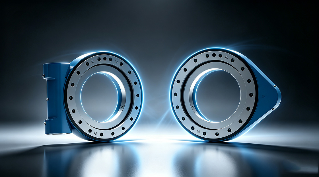
Choose bearing construction for the load pattern, not catalog familiarity
Different bearing designs distribute load differently. Single Row Slewing Ring Ball Bearings can suit many moderate-load rotating platforms where compact arrangement and simple installation are useful. They are not automatically the best fit for high overturning moment, severe shock, or demanding accuracy requirements.
Three-row Roller Slewing Bearings are generally selected where high load capacity and separation of load paths are needed. This can fit heavy lifting and large machinery, but the larger system size, mounting requirements, and total equipment cost must be considered. The design should be selected from the actual load combination, not from the assumption that more rows always mean longer life.
For applications where rotation accuracy and stiffness drive the decision, crossed-roller or other specialized configurations may deserve review. The limit is that precision depends on the whole assembly, including mounting surfaces, drive backlash, structural deflection, and installation quality.
Common Datasheet Misreadings That Change the Selection Result
The most costly error is comparing ratings from different suppliers without confirming identical rating conditions. One manufacturer may publish a static limit, while another may present a load-curve boundary or an application-based recommendation. Those numbers cannot be treated as directly equivalent without technical clarification.
- Using one maximum rating at a time: This misses combined axial force, radial force, and tilting moment. Use the combined-load diagram whenever the payload is offset or side forces exist.
- Ignoring the load arm: Weight alone does not describe overturning moment. Include the distance from the bearing center to every major load source.
- Assuming slow rotation means low wear: Slow, repeated oscillation can repeatedly load the same raceway zone. Describe partial-angle movement and reversal frequency.
- Checking the bearing but not the gear: A geared ring also needs pinion-force, lubrication, and backlash review. This applies to driven platforms and equipment with frequent starts and stops.
- Ignoring support-frame deflection: A flexible flange can concentrate load into a small portion of the raceway. Provide mounting details for supplier review.
- Using peak load as the only duty input: Peak events set one limit, while frequent operating loads influence fatigue life. Provide both values as separate operating states.
A practical supplier review should result in more than a part number. Ask for the proposed bearing model, load-combination basis, mounting requirements, gear information if applicable, sealing and lubrication recommendations, and any assumptions that could change the result. This helps purchasing teams compare quotations on engineering scope rather than price alone.
Luoyang Slewring Bearing Co., Ltd. operates an ISO 9001:2015 certified facility with six production lines and an annual capacity of 100,000 sets. Every slewing bearing passes CMM three-coordinate inspection and dynamic load testing under our quality-control process. These controls support consistent manufacturing, but the customer’s actual duty cycle remains the basis for correct model selection.
Use a Complete Load Package When Requesting a Bearing Proposal
The best time to resolve rating questions is before drawings are frozen and before procurement compares suppliers. A clear load package gives engineers enough information to recommend a standard bearing, a modified configuration, or a Customized Slew Drive when the application needs an integrated solution.
| Information to provide | Why the supplier needs it | What can change if it is missing |
|---|---|---|
| Axial, radial, and moment loads for each operating state | Supports combined-load evaluation. | The selected size may be based only on isolated values and may not match the real duty. |
| Load locations and center-of-gravity positions | Determines tilting moment and changing load direction. | Offset loading may be underestimated. |
| Rotation angle, frequency, direction changes, and operating schedule | Helps distinguish fatigue duty from occasional positioning. | Service-life assessment may be overly optimistic or unnecessarily conservative. |
| Mounting drawing and bolt arrangement | Allows review of support stiffness and fastening interface. | Ring distortion and bolt-joint concerns may remain hidden. |
| Environment and maintenance access | Guides sealing, corrosion protection, lubricant, and inspection planning. | The selected configuration may not suit dust, moisture, or corrosion exposure. |
A real application example shows why system conditions matter. A South Korean port equipment manufacturer placed a repeat order for WEA9-62-25HR single worm slew drives used in port crane systems. That stated application required self-locking behavior, IP65 sealing, and tracking precision of no more than 0.15 degrees; those requirements apply to that project and should not be treated as universal values for every crane design.
For a different duty pattern, a customer in British Columbia selected WED14-86-25BHR.5 double worm slew drives for forestry grapple machines, with stated precision of no more than 0.13 degrees. The example illustrates that load type, control requirement, environmental exposure, and drive arrangement must be reviewed together.
When reviewing a slew bearing datasheet, treat axial capacity, radial capacity, and moment capacity as connected parts of one load case. Add duty cycle, mounting stiffness, gear loading, and environmental conditions before approving the bearing. That method produces a more reliable service-life decision than selecting the largest catalog rating.
Request Your Custom Slew Drive or Bearing Spec
Tell us your load, speed, and environment — receive a tailored 100–5000 mm slewing drive or slewing bearing proposal with 3D drawings within 24 hours.
 WhatsApp

 +8613903880726