



What is a slew bearing drawing? It is the controlled engineering document that defines the bearing envelope, mounting interfaces, gear arrangement, bolt locations, and other dimensions needed to connect a slewing bearing to its housing and rotating structure.
Before a machine shop cuts a housing, flange, turntable, or support frame, the design team must answer one question: which dimensions control the interface? A slew bearing drawing may show dozens of numbers, but only a smaller group determines whether the bearing mounts flat, rotates freely, carries load as intended, and can be serviced later.
This guide helps OEM engineers, project managers, and procurement teams review a supplier drawing before releasing mating parts. The intended result is simple: your fixed structure and rotating structure should match the bearing’s datum surfaces, mounting faces, raceway position, bolt pattern, and gear clearance requirements.
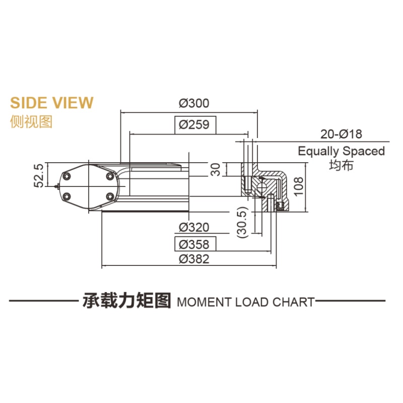
Start with the drawing revision, product configuration, and missing inputs
Do not begin by transferring dimensions into a housing model. First confirm that the drawing represents the exact bearing configuration approved for the project. A drawing for an externally geared unit is not interchangeable with an internally geared or gearless version, even when the outside diameter appears similar.
For a purchased Slewing Bearing, check the document header and compare it with the purchase specification, 3D model, and supplier quotation. Stop the release process if the part number, revision, gear type, mounting hole arrangement, or interface orientation does not match.
Information required before you release machining
| Required input | What to verify | Why it affects machining | What to do if missing |
|---|---|---|---|
| Part number and drawing revision | Exact model, revision letter or number, and issue date | Prevents machining to an outdated interface | Request the current controlled drawing from the supplier |
| Gear configuration | External gear, internal gear, or no gear | Changes clearance, pinion location, and guarding requirements | Hold the mating-part release until confirmed |
| Mounting arrangement | Which ring mounts to the base and which ring mounts to the rotating member | Prevents reversed bolt access and blocked fastener installation | Mark fixed and rotating sides in the assembly model |
| Load and operating condition | Axial load, radial load, overturning moment, speed, duty cycle, and environment | Determines whether the selected bearing type and support stiffness are suitable | Send operating data for engineering review |
| Lubrication and service access | Grease fitting position, plug access, bolt access, inspection space | Prevents a maintainable bearing from becoming inaccessible after assembly | Review the complete machine envelope |
The part number is the first gate. The second is the assembly orientation. A bearing can be dimensionally correct yet impossible to install if a flange blocks the mounting bolts or a gearbox occupies the grease fitting area.
For heavy cyclic-load applications, also confirm the bearing type before building interfaces. A Three-row Roller Slewing Bearing has different load paths and installation considerations from a light-duty ball-bearing arrangement. Do not select the support structure based on outside diameter alone.
Luoyang Slewring Bearing Co., Ltd. provides technical proposals within 24 hours when the application data is available. That review is most useful before steel cutting, not after a machined ring has already failed inspection.
Trace datum surfaces, mounting faces, raceway positions, and critical dimensions before releasing mating parts
This is the interface-control step. Treat the bearing drawing as a chain of references, not as a list of isolated dimensions. Your housing and rotating flange must be located from the same functional surfaces that locate the bearing rings.
Use the following sequence before releasing a mating part to machining.
- Identify the fixed ring and rotating ring. Read the section view, mounting-hole callouts, and gear location. Mark one ring as the stationary connection and the other as the rotating connection in your assembly model. This step fits every bearing installation. It does not replace checking the supplier’s stated installation direction.
- Find the two mounting faces. These are the flat ring surfaces that contact the machine structure. Trace each face across the sectional view and label it “base interface” or “rotating interface.” Do not use an adjacent shoulder, seal cover, or gear face as the seating reference unless the drawing explicitly identifies it as a mounting face.
- Establish the axial datum. Select the machine face that contacts the bearing mounting face as the controlled axial reference. Dimension support heights, pinion locations, and adjacent components from that face. This prevents stack-up error caused by measuring from unmachined plate edges or cosmetic surfaces.
- Establish the radial center. Use the drawing center axis and the applicable inner or outer locating diameter. Build the housing bore, pilot, or locating feature concentric to that axis. A bolt circle alone should not be your only centering method because bolt clearance can permit unwanted radial movement.
- Locate the raceway position. In the section view, identify where the rolling elements run relative to the mounting faces. Record the axial distance from each mounting face to the raceway center region when it is shown or supplied. This is needed when checking support stiffness and preventing a thin flange from bending directly beneath the loaded zone.
- Transfer mounting-hole data. Verify hole quantity, bolt circle diameter, hole type, thread condition, and whether holes belong to the inner ring or outer ring. Check the first-hole orientation if the drawing includes it. Incorrect clocking can block a grease fitting, motor bracket, or pinion support.
- Check gear and seal clearances. For geared bearings, maintain physical clearance around the gear teeth and pinion path. For sealed areas, do not add a locating lip that contacts the seal. The bearing may turn by hand during initial assembly but fail after deflection if clearance is inadequate.
- Release only the controlled interface dimensions. Put the mounting face flatness requirement, locating diameter, bolt pattern, concentricity relationship, and assembly orientation on the mating-part drawing. Keep nonfunctional dimensions separate from these interface controls.
Use this trace table during drawing review
| Feature on supplier drawing | Feature on mating part | Inspection checkpoint | Failure if ignored |
|---|---|---|---|
| Upper mounting face | Rotating flange seating face | Face is continuous, clean, and free of weld distortion | Ring distortion, uneven bolt loading, rough rotation |
| Lower mounting face | Base-frame or housing seating face | Face is machined from the same axial datum used in the assembly | Axial stack-up error and mislocated equipment |
| Inner or outer locating diameter | Machined pilot or bore | Center axis aligns with the intended rotation axis | Runout, uneven gear mesh, or shifted load path |
| Bolt circle and hole pattern | Threaded holes or clearance holes | Quantity, pattern, and orientation match the correct ring | Blocked bolts, forced assembly, or missing fasteners |
| Raceway location in section view | Support wall and flange geometry | Load path has adequate structural support beneath the ring | Local deflection and reduced bearing life |
The conclusion is direct: machine the interface from functional datums, not from the drawing’s overall envelope dimensions. Overall height and outside diameter are useful checks, but they do not always control how the ring seats or where the raceway load enters the structure.
At Luoyang Slewring Bearing Co., Ltd., material selection can include ductile cast iron, alloy steel, stainless steel, or forged alloy steel according to load, speed, and environment. That same application data should guide the design of the mating structure. The bearing ring may be suitable, while a thin or poorly supported customer flange remains the weak point.
Request Your Custom Slew Drive or Bearing Spec
Tell us your load, speed, and environment — receive a tailored 100–5000 mm slewing drive or slewing bearing proposal with 3D drawings within 24 hours.
Read the section view before relying on the top view
The top view usually makes bolt circles and gear position easy to see. The section view explains how the bearing actually carries load. Read both views together, but give the section view priority when machining a housing or support structure.
Start at one mounting face and follow the load path inward: support structure, bearing ring, raceway, rolling elements, opposing raceway, second ring, and rotating structure. If your model interrupts this path with gaps, narrow contact bands, unsupported plate, or weld distortion, the assembly needs review before production.
Questions to ask while reading the cross-section
- Where does axial load enter? The answer shows which flange face must remain flat under operating load. This matters for lifting equipment, turntables, and rotating platforms. It may be less dominant in a lightly loaded positioning system, but the mounting faces still require proper support.
- Where does overturning moment enter? Moment loading acts through the ring spacing and support structure. A broad, well-supported mounting surface generally distributes load better than a narrow flange. The final flange design still requires application-specific engineering.
- Is there a gear? An external or internal gear needs a defined pinion engagement zone. Do not position a welded gusset, sensor bracket, or hose routing path where it can interfere with the teeth or pinion.
- Where are the seals and grease points? These features need access and clearance. They are not structural locating surfaces.
- Which dimensions are reference dimensions? Parenthesized or reference-only values should not automatically become machining dimensions. Follow the drawing’s toleranced and controlled callouts.
A practical example is a turntable with an externally geared bearing. The base structure supports one ring, while the upper platform supports the other. The pinion center must be set from the gear geometry and bearing center axis, not from the outside edge of the fabricated platform. Using the fabricated edge can shift the mesh if the edge is not concentric with the bearing center.
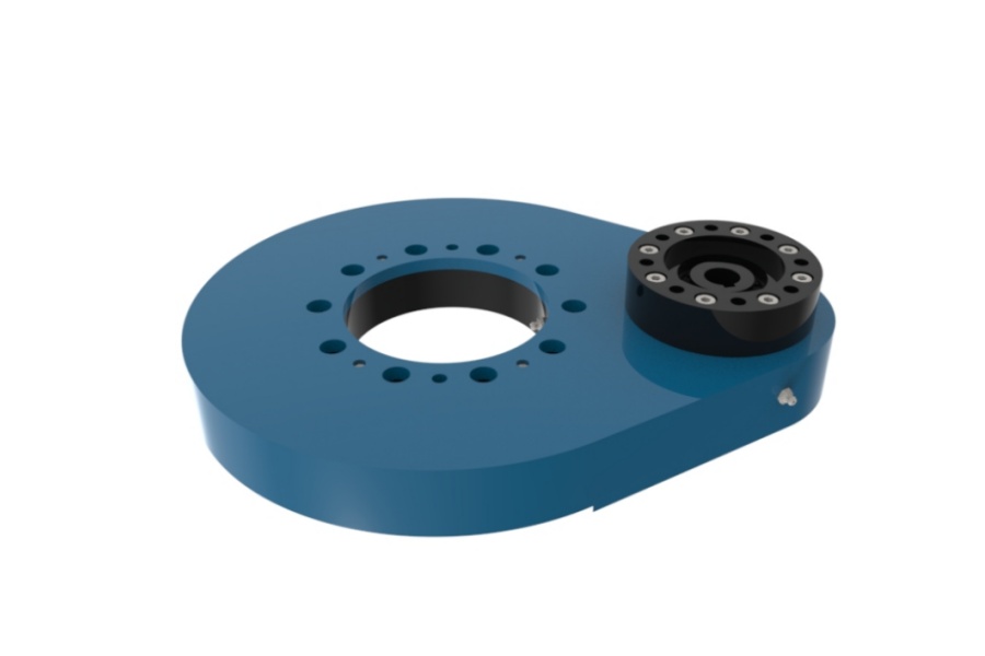
For a powered rotation system, the drawing review must also include the drive. A Worm Gear Slew Drive integrates a slewing bearing and worm transmission in one housing, so its mounting surfaces, motor position, and output interface must be reviewed as a complete unit rather than as a separate bearing and gearbox.
Separate controlled dimensions from reference dimensions and shop assumptions
Not every number on a drawing has the same authority. The shop should machine from dimensions that define functional interfaces, tolerances, datums, and explicit notes. It should not infer functional requirements from a scaled PDF image or an untoleranced visual feature.
Use this decision rule: if changing a dimension could alter seating, centering, bolt installation, gear mesh, seal clearance, or load transfer, it belongs on the controlled-interface review list. If it only changes the external appearance or noncontact envelope, it may be a secondary check.
Common drawing-reading mistakes and their recovery actions
- Mistake: Centering the housing from bolt holes only. Bolt clearances can allow radial shift. Recover by identifying the intended locating diameter or pilot feature and revising the housing datum scheme.
- Mistake: Treating a seal edge as a mounting shoulder. The seal can be damaged during installation or operation. Recover by tracing the actual ring mounting face in the section view and adding clearance around the seal zone.
- Mistake: Copying an old hole pattern. Similar bearing sizes can have different bolt quantities or clocking. Recover by comparing the current controlled drawing, part number, and revision before drilling.
- Mistake: Ignoring fastener tool access. A correct bolt pattern can still be impossible to tighten. Recover by modeling sockets, washers, and wrench access around both rings.
- Mistake: Designing a support flange from outside diameter. The outer envelope may not show the functional raceway position. Recover by reviewing the cross-section and supporting the ring where load enters the structure.
- Mistake: Releasing fabrication before the bearing drawing is approved. Weld shrinkage and rework can become expensive after machining. Recover by holding final machining until the drawing revision and interfaces are signed off.
These checks are especially relevant for customized equipment. A Customized Slew Drive or special bearing interface may need a nonstandard mounting pattern, special corrosion protection, or a revised envelope. Standard product orders can start from one set, while customized product orders have a five-set minimum, so it is wise to settle the interface before committing to a custom release.
Verify the assembly model with a pre-machining checklist
Complete this checklist using the supplier drawing, your assembly CAD model, and the mating-part manufacturing drawing. A pass means the design is ready for formal release. A failed item means return to the drawing review or request clarification before chips are made.
- Part identity passes: the bearing model, supplier drawing, CAD model, and bill of materials use the same part number and revision.
- Orientation passes: fixed ring, rotating ring, gear side, grease fitting access, and bolt access are shown in the assembly.
- Mounting-face check passes: each ring has a continuous machined seating surface without weld beads, paint buildup, or unsupported gaps.
- Centering check passes: the selected locating feature is concentric with the intended machine rotation axis.
- Bolt-pattern check passes: hole count, bolt circle, thread condition, and first-hole orientation match the approved drawing.
- Clearance check passes: gears, seals, plugs, grease fittings, tools, guards, and nearby structures have usable clearance.
- Load-path check passes: the support structure is reviewed against the expected axial, radial, and moment loads rather than only the bearing envelope.
- Inspection-plan check passes: the shop knows which face, diameter, and bolt pattern are functional inspection features.
For high-consequence equipment, include the bearing supplier in the final interface review. Luoyang Slewring Bearing Co., Ltd. operates an ISO 9001:2015 certified facility and uses CMM three-coordinate inspection and dynamic load testing for slewing bearings. Those controls verify the supplied component; the OEM still needs to verify that its machined structure matches the approved interface.
Match the review depth to the application and bearing design
Not every project needs the same level of interface analysis. A low-load manual turntable and a crane or excavator rotating structure have very different consequences if the mounting interface distorts. The correct approach is to increase review depth as load, duty cycle, safety exposure, and service difficulty increase.
| Application condition | Recommended review focus | When this approach is not enough |
|---|---|---|
| Light-load positioning equipment | Confirm bolt pattern, mounting faces, center axis, and service access | Not enough when repeated moment loads or high positioning accuracy are involved |
| Automated turntable | Add runout, gear or drive alignment, cable routing, and cycle-duty review | Not enough when the system handles high shock loads |
| Truck crane or marine crane | Add support stiffness, bolt access, load path, corrosion exposure, and maintenance planning | Not enough without application load data and supplier engineering input |
| Mining or heavy equipment | Add fatigue duty, impact loading, structural deflection, and assembly inspection controls | Not enough without a full machine-level structural analysis |
Real application results show why the interface matters. A British Columbia forestry equipment manufacturer used WED14-86-25BHR.5 double worm slew drives for forestry grapple machines with tracking precision of no more than 0.13 degrees. That result applies to the stated project, not every installation, but it shows why center location, mounting accuracy, and drive alignment must be treated as linked design tasks.
For corrosion-exposed equipment, confirm more than geometry. Luoyang Slewring Bearing Co., Ltd. can provide slew drives with protection up to IP66 and anti-corrosion ratings up to C4H, depending on the specified product and working condition. These features do not remove the need to prevent standing water, blocked grease access, or interference around seals.
Release machining only after the functional interfaces are closed
A completed drawing review should leave no uncertainty about four items: where each ring seats, how the bearing is centered, where the raceway load enters the structure, and how bolts and service tools reach the assembly. If any of these remain unclear, the drawing is not ready for mating-part release.
Use the supplier drawing as the authority for the bearing interface, then place those requirements into your housing and flange drawings with clear datum references. Keep the bearing revision in the assembly record. This protects the project if a later design change affects bolt locations, gear arrangement, or installation direction.
Lewis, Senior Mechanical Design Engineer, applies this review method across heavy machinery and power transmission work, including slewing bearings, slew drives, cranes, medical imaging platforms, and industrial automation lines. The goal is not to add drawing paperwork. It is to prevent an avoidable mismatch between a precision bearing and the structure built around it.
Request Your Custom Slew Drive or Bearing Spec
Tell us your load, speed, and environment — receive a tailored 100–5000 mm slewing drive or slewing bearing proposal with 3D drawings within 24 hours.
 WhatsApp

 +8613903880726