



Edge loading concentrates an application's entire force onto a very small area of a bearing's raceway, dramatically accelerating slew bearing wear and leading to premature failure. Instead of the load being distributed smoothly across multiple rolling elements in the center of their intended path, it is focused on the sharp edge of the raceway. This concentration of force quickly exceeds the material's design limits, causing plastic deformation, surface fatigue, and spalling that can destroy a bearing in a fraction of its expected service life.
In my three decades as a mechanical design engineer, I have analyzed countless bearing failures. More often than not, the root cause isn't a defect in the bearing itself but a problem with the surrounding structure or installation. Understanding how edge loading occurs is the first step for any OEM design team or maintenance engineer looking to improve equipment reliability and longevity.
Understanding Ideal Load Distribution in a Slewing Bearing
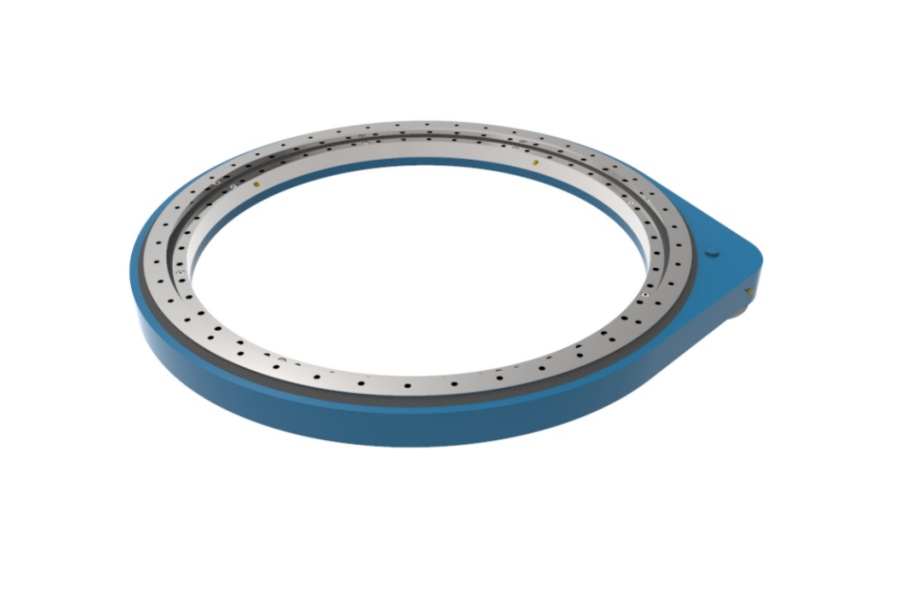
A slewing bearing is designed to operate under the principle of Hertzian contact stress. This means that when a spherical or cylindrical rolling element (a ball or roller) presses against the curved raceway under load, the contact area is not a single point but a small, well-defined elliptical or rectangular patch. The load is distributed evenly across this patch.
In a properly mounted and loaded system:
- Load is Shared: The total axial, radial, and moment loads are distributed across numerous rolling elements within the bearing's load zone.
- Contact is Centered: Each loaded rolling element makes contact in the center of the raceway, where the geometry is optimized for stress distribution and smooth rolling.
- Stress Remains Elastic: The contact stresses are high but remain within the material's elastic limit. This means the steel deforms slightly under load and returns to its original shape once the load is removed, allowing for a long fatigue life.
This ideal distribution is the foundation of a bearing's L10 life calculation. Any deviation from this centered, distributed contact pattern can drastically shorten the operational lifespan of the component.
When Mounting Stiffness and Moments Concentrate Stress
The transition from normal wear to accelerated failure occurs when the bearing's rings are forced to deflect from their intended circular, flat plane. This deflection is almost always caused by two interconnected factors: an insufficiently stiff mounting structure and high overturning moments. This combination forces the rolling elements to ride on the edge of the raceway, where contact stress can increase exponentially.
A non-rigid support structure will flex under load, distorting the bearing ring bolted to it. This seemingly minor distortion is enough to shift the internal load path. High overturning moments—common in applications like excavators, cranes, and wind turbines—try to lift one side of the bearing while compressing the other, which further concentrates the entire load on just a few rolling elements at the raceway edge.
The table below breaks down how these conditions lead to destructive edge loading.
| Mounting Condition | Raceway Contact Stress Pattern | Resulting Wear Type | Impact on Service Life |
|---|---|---|---|
| Flat & Stiff Structure (Ideal) |
Broad, elliptical contact patch centered on the raceway. Load is shared by multiple rolling elements. | Normal, gradual surface fatigue and abrasive wear over a long period. | Achieves or exceeds calculated L10 bearing life. |
| Non-Stiff or Uneven Structure | Contact patch shifts to the inner or outer edge of the raceway. Stress is concentrated on a narrow line. | Localized plastic deformation, rapid pitting, and spalling at the raceway edge. | Drastic reduction in life; failure can occur at 10-30% of expected life. |
| High Overturning Moment | Load is concentrated on a small number of rolling elements on one side of the bearing, at the very edge of the raceway. | Severe edge spalling, potential for cage failure, and increased rotational torque. | Catastrophic failure is possible. The bearing may seize or lose rotational accuracy quickly. |
At Luoyang Slewring Bearing Co., Ltd., our engineering team frequently assists customers by reviewing their mounting structure designs. By providing a technical proposal within 24 hours, we can help identify potential stiffness issues before manufacturing begins, preventing costly failures in the field.
Request Your Custom Slew Drive or Bearing Spec
Tell us your load, speed, and environment — receive a tailored 100–5000 mm slewing drive or slewing bearing proposal with 3D drawings within 24 hours.
Common Causes of Edge Loading and How to Identify Them
Edge loading is an application-level problem, not a bearing defect. Our ISO 9001:2015 certified manufacturing process, which includes CMM three-coordinate inspection for every bearing, ensures that the component geometry is correct when it leaves our factory. The problems arise from how the bearing interacts with the machine it's installed in. Here are the most common mistakes to avoid.
Checklist for Preventing Edge Loading
-
Is the support structure sufficiently stiff?
The structure to which the Slew Bearing is mounted must be rigid enough to resist deflection under maximum load. A common error is designing a structure that is strong enough but not stiff enough. This is especially critical for equipment with long booms or arms, like cranes and excavators.
-
Is the mounting surface perfectly flat and clean?
Any deviation from flatness—caused by weld distortion, machining errors, or even a stray piece of grit or a paint chip—creates high spots. When the bearing is bolted down, these high spots act as fulcrums, bending the bearing ring and creating an internal misalignment that guarantees edge loading.
-
Is the bolt preload correct and evenly applied?
Mounting bolts must be tightened to the correct torque specification using a calibrated torque wrench. More importantly, they must be tightened in a star or crisscross pattern in multiple stages (e.g., 30%, 70%, 100% of final torque). Tightening bolts sequentially around the circle will warp the bearing ring, a condition known as "potato chipping."
-
Are overturning moments within the bearing's capacity?
Every bearing has a load chart defining its capacity to handle overturning moments. Dynamic loads, especially in mobile equipment, can cause spikes in moment loads that exceed the static rating. If an application consistently operates near or beyond this limit, a stiffer bearing, such as a Three-row Roller Slewing Bearings, may be required.
Analyzing Wear Patterns to Diagnose the Root Cause
When a bearing fails prematurely, the wear patterns on the raceway are a clear record of what went wrong. By carefully inspecting the location and type of damage, maintenance teams can accurately diagnose the problem and implement a lasting solution.
Here’s what to look for:
- Wear Pattern: Spalling at One Edge of the Raceway
If you see a continuous band of pitting, flaking, or spalling along the inner or outer edge of one of the raceways, it is a definitive sign of constant edge loading. This is typically caused by a permanently distorted or non-flat mounting surface. - Wear Pattern: Intermittent Damage Around the Circumference
When the wear marks appear at specific intervals around the bearing—for example, at each mounting bolt location—it often points to incorrect bolt torqueing or a "wavy" mounting surface with distinct high and low spots. - Wear Pattern: Damage on Opposite Sides
If you find heavy wear on one side of the inner ring raceway and the diametrically opposite side of the outer ring raceway, the primary culprit is an excessive overturning moment. This pattern shows where the bearing was being pinched and compressed under the high moment load.
Recognizing these patterns helps differentiate between an installation issue and a lubrication or contamination problem, ensuring that corrective actions address the true root cause of the accelerated slew bearing wear.
Mitigation Strategies for Heavy-Duty Applications
Preventing edge loading requires a systematic approach that begins at the design stage and continues through installation and operation. For heavy-duty equipment, where loads are high and downtime is expensive, these steps are not optional.
First, conduct a Finite Element Analysis (FEA) of the mounting structure. This computer simulation will predict how the structure will deform under operational loads and can verify that the mounting surface for the bearing will remain flat and rigid.
Second, enforce strict machining and cleanliness standards for the mounting surfaces. Specify a flatness tolerance and surface finish in the design drawings, and ensure these are verified before installation. The surfaces must be completely free of paint, rust, dirt, and any other contaminants.
Finally, select a bearing designed for the application's specific loads. While a Light Load Slewing Bearing is suitable for some applications, machinery with high overturning moments requires a more robust solution. This is why customers in demanding industries rely on our expertise. For example, a South Korean port equipment manufacturer uses our WEA9 single worm slew drives for their port crane systems. These units must handle significant wind and cargo loads while maintaining a tracking precision of less than 0.15°, a performance metric made possible by a rigid bearing design that resists deflection. Similarly, our HWE21 double worm slew drives are used by an Australian heavy equipment manufacturer in mining excavators, where extreme shock loads and moments are an everyday occurrence. These successful applications are built on a foundation of correct bearing selection and proper system integration.
By treating the slewing bearing and its support structure as a single integrated system, engineers can effectively eliminate edge loading and ensure their equipment achieves its designed service life.
Request Your Custom Slew Drive or Bearing Spec
Tell us your load, speed, and environment — receive a tailored 100–5000 mm slewing drive or slewing bearing proposal with 3D drawings within 24 hours.
 WhatsApp

 +8613903880726