


Understanding Self-Locking in Worm Gear Slew Drives
What is a Worm Gear Slew Drive?
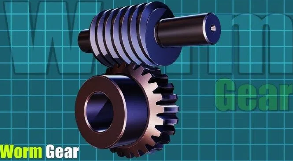
A worm gear slewdrive is a compact, geared mechanism designed to handle heavy radial and axial loads while providing precise rotational motion. It is essentially a gearbox that integrates a worm screw (also called the worm) and a worm wheel (also called the slewing ring) into a single unit. This combination allows it to transmit torque around a central axis, making it ideal for applications that require slow, controlled, and powerful rotation. Unlike standard gearboxes, slew drives are built to support substantial loads directly, eliminating the need for external bearings in many cases.
How Does a Worm Gear Slew Drive Work?
The operating principle of a worm gear slew drive is simple yet highly effective. The worm, which is a cylindrical threaded shaft, acts as the input. When a motor turns this worm, its threads mesh with the teeth on the circumference of the worm wheel. As the worm rotates, it pushes the teeth of the wheel, causing the wheel to rotate.
This meshing action creates a significant speed reduction. For every full rotation of the worm, the worm wheel only rotates by a fraction of a turn, depending on the number of teeth on the wheel. This high reduction ratio is what allows the drive to multiply torque, enabling a small motor to move or hold a very heavy load. The right-angle configuration of the input shaft (worm) and output shaft (wheel) also allows for flexible and space-saving system design.
Design Features of Worm Gear Slew Drives
Several key design features distinguish worm gear slew drives and contribute to their performance:
Integrated Slewing Ring Bearing: The worm wheel is typically integrated into a large-diameter bearing (the slewing ring). This allows the drive to directly support axial, radial, and moment loads from the structure above, such as a crane boom or a solar panel array.
Right-Angle Configuration: The input worm is perpendicular to the output wheel, providing a compact, 90-degree drive solution.
Housing and Mounting: The worm and a portion of the wheel are enclosed in a durable housing that contains lubrication and protects components from the environment. The housing includes standard mounting flanges for easy integration.
Material Selection: The worm is typically made of hardened steel for strength and wear resistance. The worm wheel is often made of a bronze alloy or ductile iron, which has excellent bearing properties and a low coefficient of friction when run against the hardened steel worm.
Sealing: High-quality seals are used to retain lubricant and prevent ingress of contaminants like dust, water, and debris, which is crucial for long-term reliability in harsh environments.
What is "Self-Locking" in a Worm Gear Slew Drive?
"Self-locking," also known as "back-driving prevention," is a critical characteristic of many worm gear slew drives. In simple terms, it means that when the driving force (the motor) is stopped, the load attached to the output (the worm wheel) cannot rotate the worm backward. The drive effectively locks itself in place.
This phenomenon is purely a function of friction and geometry. It occurs when the friction angle between the worm and the worm wheel is greater than the lead angle of the worm thread. When this condition is met, the force of the load trying to spin the wheel is not enough to overcome the static friction holding the worm and wheel together. Instead of the wheel turning the worm, the gears simply bind, holding the load securely.
This is in contrast to a non-self-locking drive, where a load on the output would simply spin the worm backward (back-drive) as soon as the motor is disengaged. Self-locking provides a natural, inherent braking effect without the need for an external mechanical brake, offering safety and simplicity in design.
Key Factors Affecting the Self-Locking Function of Worm Gear Slew Drives
The self-locking function is not a fixed property; it is determined by the interplay of several key design parameters and operating conditions. These can be grouped into three main categories:
5.1 Intrinsic Design Parameters
The Helix Angle (Lead Angle): This is the single most important design factor. The helix angle is the angle that the worm thread makes with a line perpendicular to the worm's axis. A small (shallow) helix angle is the geometric foundation for self-locking. Typically, a helix angle of 5 to 6 degrees or less is required for effective self-locking. If the angle is steeper, the gear set will tend to back-drive easily, much like it is easier to roll down a steep hill.
Gear Ratio: The gear ratio is intrinsically linked to the helix angle. A higher gear ratio (e.g., 30:1, 40:1, or higher) is achieved with a worm that has a smaller helix angle and fewer threads. Therefore, high-ratio worm gear sets are almost always self-locking. Conversely, low-ratio sets (e.g., 5:1 to 10:1) have steeper helix angles and are typically not self-locking, meaning they can be back-driven.
Number of Starts: The number of starts on a worm refers to the number of independent threads wrapped around the cylinder. A single-start worm has one continuous thread and a shallow lead angle, making it the standard choice when reliable self-locking is a primary requirement. Multi-start worms (double-start or more) have steeper lead angles for a given diameter, allowing for faster output speeds but significantly reducing or eliminating the self-locking ability.
5.2 Tribological Factors
Material Pairing & Surface Finish: The self-locking condition is mathematically expressed as the static friction angle needing to be greater than the helix angle. This friction angle is determined by the coefficient of static friction between the worm and wheel materials. A hardened steel worm running against a bronze wheel creates a specific, desirable friction coefficient. The surface finish also plays a role; smoother surfaces can reduce friction, potentially undermining self-locking, while rougher surfaces increase friction, aiding the locking mechanism.
Lubrication: Lubrication is a critical double-edged sword. It is essential for reducing wear, dissipating heat, and ensuring efficient operation. However, the specific lubricant chosen directly affects the coefficient of friction between the gear teeth. A high-friction lubricant can enhance self-locking, while a low-friction synthetic oil might reduce friction to the point where a marginally self-locking drive can be back-driven. The lubricant's viscosity and additive package are, therefore, critical considerations.
5.3 Operational & Environmental Influences
Vibration and Dynamic Loads: This is the most common external threat to a self-locking mechanism. The self-locking mechanism is most reliable under static, steady-state loads. External vibrations, shock loads, or oscillations can momentarily break the static friction contact between the teeth. During these micro-moments of separation, the condition shifts from static friction (high) to dynamic friction (lower). If the dynamic friction is low enough, the load can cause the wheel to slip and back-drive the worm, even if the drive is self-locking under a perfectly still load. Heavy machinery operation, wind gusts, or system-induced vibrations are common culprits.
Applications of Self-Locking in Worm Gear Slew Drives
The inherent safety and holding power of self-locking worm gear slew drives make them invaluable across a wide range of industries:
Lifts & Elevators: In scissor lifts, material lifts, and some personnel lifts, a self-locking slew drive is used to raise and lower the platform. The self-locking feature acts as a critical safety mechanism, ensuring the platform cannot crash down if the power fails or the drive cable breaks.
Hoists & Winches: For applications like crane hoists, boom articulation, and winch drums, holding the load is paramount. A self-locking slew drive on the hoist drum prevents the load from unwinding under gravity. This provides a secure hold during lifting, holding, and lowering operations without constant brake engagement.
Musical Instruments: A fascinating application is in large pipe organs or mechanical musical instruments. Self-locking worm drives are used to precisely position heavy components like wind chests or to rotate elaborate percussion mechanisms. They hold the position perfectly against gravity and vibration, ensuring the instrument stays in tune and operates reliably.
Conveyor Systems: In inclined or vertical conveyors, or in systems with accumulating loads, a self-locking drive on the head pulley prevents the belt from rolling backward when the motor is off. This prevents material from spilling back or piling up at the infeed, ensuring a clean and controlled restart.
Solar Tracking Systems: While many solar trackers use high-efficiency drives, some designs utilize self-locking worm drives to hold large solar panel arrays in position against strong winds. The drive's natural resistance to back-driving prevents wind forces from moving the panels, protecting them and maintaining optimal alignment.
Mobile Equipment (e.g., Aerial Work Platforms): The rotation of the platform's turntable is often driven by a self-locking slew drive. This ensures that the platform, with personnel and equipment aloft, remains securely oriented and cannot be spun around by wind, movement, or off-center loads.
Limitations of Self-Locking in a Worm Gear Slew Drive
Despite its usefulness, relying on self-locking has important limitations that engineers must consider:
Not a Substitute for a Safety Brake in Critical Applications: This is the most important limitation. The self-locking mechanism is friction-based and can fail. The American Gear Manufacturers Association (AGMA) and standard engineering practice strongly advise against relying solely on the self-locking feature for safety-critical applications like personnel lifts. An independent, positive-engagement mechanical brake (like a disc or drum brake) is mandatory for fail-safe operation.
Sensitivity to Lubrication and Wear: As discussed, the self-locking function depends on a specific coefficient of friction. If the wrong lubricant is used, or if the lubricant degrades or leaks out, the friction can change. Similarly, significant wear on the gear teeth over time can alter the geometry and surface finish, potentially compromising the self-locking ability.
Unreliability Under Dynamic Conditions: Vibration and shock loads can defeat self-locking, as explained in Section 5. In applications with inherent vibration, the drive may intermittently slip, leading to position loss or uncontrolled movement.
Lower Efficiency: The high friction that enables self-locking also makes the drive less efficient. A significant amount of input energy is lost as heat. This means a larger motor may be needed compared to a non-self-locking, higher-efficiency drive for the same output torque.
Thermal Issues: The energy lost to friction is converted into heat. In continuously running or high-duty-cycle applications, a self-locking worm drive can generate significant heat, potentially requiring special lubricants, cooling fins, or even forced cooling to prevent overheating and damage.
LyraDrive: Get Your Worm Gear Slew Drive 3D Drawing for Your Application
Selecting the correct worm gear slew drive—with the right load capacity, self-locking characteristics, and dimensional fit—is critical to your project's success. At LyraDrive, we are a professional manufacturer specializing in high-quality slew drives and slewing bearings.
Our worm gear slew drives are engineered with inherent self-locking capability, making them the preferred choice for applications where safety and position holding are critical—such as holding platforms steady in aerial lifts, preventing load drift in crane hoists, and maintaining panel alignment against wind forces in solar trackers. This reliable, friction-based braking action ensures operations remain safe and stable, even under challenging conditions.
Streamlining Your Design with 3D Technology:
We believe in getting the design right before manufacturing begins. Our 3D-powered customization process ensures a perfect fit while minimizing communication costs:
Share Your Requirements: Provide your design drawings, load specifications, and mounting requirements.
In-Depth 3D Analysis: Our engineers create a detailed 3D model, analyze load conditions, and verify system integration—identifying potential issues before production.
Receive Your 3D Drawing: We deliver a precise CAD model for your approval, allowing you to check clearances and validate the design in your assembly.
Reduce communication costs: This collaborative approach eliminates guesswork, ensuring your requirements are met efficiently and accurately the first time.
Ready to get started? Contact LyraDrive today to discuss your application and request your free 3D design consultation.
FAQ of Self-Locking in Worm Gear Slew Drives
Q1: Is a worm gear drive always self-locking?
No. Self-locking depends on the helix angle, gear ratio, and friction. Drives with high ratios (e.g., >30:1) and single-start worms are typically self-locking, while low-ratio, multi-start drives are not.
Q2: Can I rely on self-locking to hold a load safely?
For non-critical applications where a failure would not cause injury or major damage, yes. For safety-critical applications like personnel lifts, you must use an independent mechanical brake as a backup. Self-locking is a feature, not a fail-safe safety device.
Q3: Will changing the lubricant affect self-locking?
Yes, absolutely. Using a lubricant with a lower coefficient of friction than originally specified can reduce or eliminate the self-locking function. Always use the manufacturer's recommended lubricant type and viscosity.
Q4: How can I test if my slew drive is self-locking?
With the drive mounted and the input shaft disconnected from the motor, try to turn the output flange (the load-bearing part) by hand or with a lever bar. If it rotates freely, it is not self-locking. If it is impossible or extremely difficult to turn, it is self-locking under static conditions.
Q5: What is back-driving?
Back-driving is the opposite of self-locking. It occurs when a load on the output (worm wheel) forces the worm to rotate, causing the load to descend or move unexpectedly. It is the failure mode that self-locking is designed to prevent.