


Spur Gear Slew Drive for Turret Applications
What Is a Spur Gear Slew Drive for Turret Systems?
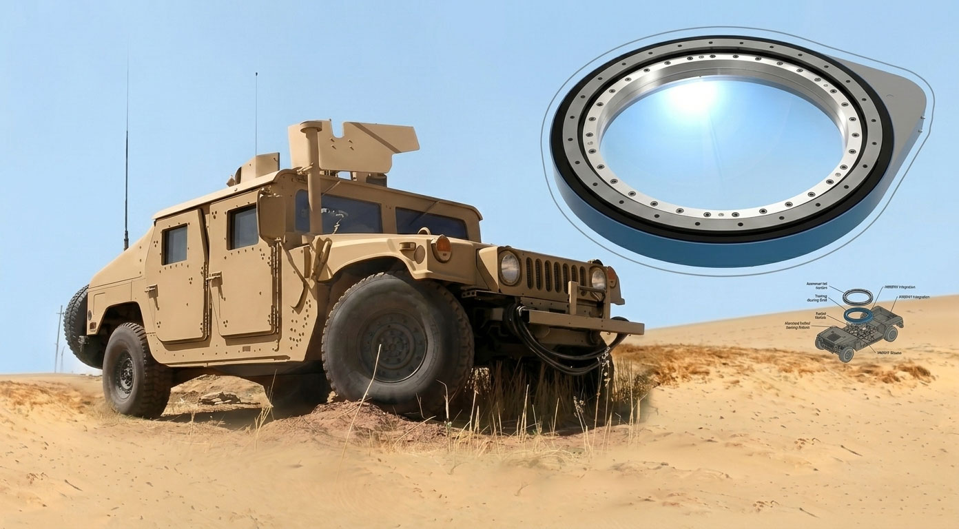
A spur gear slew drive is a compact, high-load-capacity rotating device that uses a spur gear arrangement (pinion engaging with a large internal or external spur gear ring) to enable precise rotational motion. When applied to turret systems – whether on armored vehicles, radar platforms, robotic manipulators, or optical tracking units – this drive forms the core of the turret slew drive mechanism.
Unlike worm gear slew drives, which rely on a sliding action for torque transmission, spur gear designs use direct rolling contact between gear teeth. This makes them particularly well-suited for turret applications requiring high efficiency, bi-directional rotation, and dynamic response.
Key Characteristics of Turret-Grade Spur Gear Slew Drives
Turret-grade spur gear slew drives are engineered to meet demanding operational conditions. Their key characteristics include:
High torque density – Delivers substantial rotational force in a compact footprint.
Low axial height – Ideal for space-constrained turret installations.
High efficiency – Typically 95–98% per stage, minimizing power loss.
No self-locking behavior – Allows free reverse driving, which is essential for manual override or backdrivable turret positioning.
Hardened gear teeth – Surface hardness typically 55–62 HRC for wear resistance and shock load tolerance.
Integrated housing – Often includes bearings, seals, and mounting interfaces pre-assembled.
How Does a Spur Gear Slew Drive Work in a Turret Application?
The operating principle is straightforward yet robust. First, a hydraulic motor, electric servo motor, or stepper motor drives a small pinion gear. The pinion then engages directly with a larger spur gear ring that is either integral to the turret structure or mounted to a rotating platform. The ratio between pinion and gear ring determines torque output and rotational speed – a higher ratio produces more torque but slower rotation, while a lower ratio yields faster slewing with less torque. As the pinion rotates, it walks around the gear ring, causing the turret to yaw (rotate horizontally) relative to its fixed base. Encoders or limit switches on the motor or drive output provide feedback for precise angular positioning, enabling closed-loop control.
In a typical turret configuration, the spur gear slew drive is mounted to the fixed base, while the turret structure attaches to the rotating ring (or vice versa). Multiple pinions can be used around the circumference to reduce backlash and increase load sharing – a common practice in large weapon or radar turrets where redundancy and precision are critical.
Advantages of Using Spur Gear Slew Drives in Turrets
Compared to other slew drive technologies (worm, planetary, or direct-drive), spur gear designs offer distinct benefits for turret applications. The table below summarizes the key advantages and their specific benefits for turret systems.
| Advantage | Benefit for Turret Systems |
|---|---|
| High efficiency (95–98%) | Lower motor power requirements, smaller batteries or hydraulic pumps, reduced fuel consumption on mobile platforms |
| Bi-directional operation | Symmetrical performance for clockwise and counterclockwise rotation – essential for tracking moving targets |
| No thermal runaway | Minimal heat generation even during continuous oscillation, eliminating the need for active cooling in most turrets |
| Backdrivability | Allows manual turret positioning if power fails – a critical safety feature for weapon and radar turrets |
| Simple manufacturing | Lower cost than helical or planetary alternatives for equivalent torque, making spur drives cost-effective for large turrets |
| Easy backlash adjustment | Can be tuned via pinion position or split-gear designs without disassembling the entire drive |
| Proven reliability | Decades of use in military and industrial turrets with well-understood failure modes and maintenance practices |
Beyond these specific advantages, spur gear slew drives also offer excellent stiffness-to-weight ratios and are compatible with a wide range of motors, including hydraulic, AC servo, DC brushless, and stepper types. This flexibility makes them the preferred choice for turret integrators who need to balance performance, cost, and packaging constraints.
Common Turret Types That Use Spur Gear Slew Drives
Spur gear slew drives are found across a wide spectrum of turret-based equipment. Below is a breakdown by application category.
Weapon Turrets
Spur gear slew drives are widely used in military and security weapon platforms. Specific examples include:
Remote weapon stations (RWS) – Lightweight, rapidly slewing turrets mounted on vehicles that require high efficiency and precise targeting.
Main battle tank turrets – Heavy-duty applications demanding high torque capacity and shock load tolerance from recoil forces.
Naval gun mounts – Corrosion-resistant configurations for shipborne environments, often requiring multiple pinions for load sharing.
Light armored vehicle cupolas – Compact turrets with limited interior space, benefiting from the low axial height of spur gear designs.
Radar Turrets
Radar systems rely on continuous, smooth rotation for target tracking and surveillance. Spur gear slew drives appear in:
Ground-based air defense radars – Requiring high duty cycles and stable motion for accurate target acquisition.
Shipborne surveillance arrays – Operating in saltwater environments with demanding sealing and corrosion protection requirements.
Mobile weather radar platforms – Mounted on trucks or trailers, where weight and packaging constraints favor spur gear efficiency.
Optical and Electro-Optical Turrets
Optical turrets demand low backlash and smooth motion to maintain line-of-sight stability. Common applications include:
Surveillance cameras – Pan-tilt units for perimeter security and border monitoring.
Laser designators – Precision targeting systems requiring minimal angular error and high repeatability.
Thermal imaging systems – Often integrated into larger turrets alongside visible-light cameras.
Target tracking sensors – Used in anti-aircraft or anti-tank systems, requiring rapid acceleration and deceleration.
Robotic Turrets
Industrial and service robotics incorporate spur gear slew drives for positioning and manipulation tasks. Examples include:
Industrial positioning tables – Rotary stages for assembly, inspection, or material handling.
Automated welding positioners – Heavy-load turntables that must maintain position under dynamic welding forces.
Parts handling turntables – High-cycle applications benefiting from spur gear efficiency and long service life.
Antenna Turrets
Large antenna systems require precise azimuth control, often with continuous rotation capability. Applications include:
Satellite tracking dishes – Demanding low backlash and smooth motion to maintain lock on orbiting satellites.
Microwave relay systems – Point-to-point communication turrets requiring stable positioning in windy conditions.
Telemetry antennas – Used in range tracking and data acquisition, often mounted on mobile platforms.
Simulation Turrets
Military training simulators replicate the feel and response of real turret systems. Spur gear slew drives are chosen for:
Weapons training simulators – Requiring backdrivability for instructor override and realistic manual operation.
Vehicle crew trainers – Multi-station simulators where multiple turrets must operate simultaneously with consistent performance.
Motion base platforms – Lower-load applications where smooth, quiet operation is prioritized over maximum torque.
In each of these turret types, the spur gear slew drive provides the necessary balance of speed, torque, accuracy, and durability. The specific requirements – whether shock resistance for weapon turrets, corrosion protection for naval radars, or low backlash for optical trackers – determine the final design configuration.
How to Select the Right Spur Gear Slew Drive for Your Turret
Proper selection requires careful analysis of your turret's operational parameters. Follow this step-by-step approach:
Step 1 – Define load requirements. You need to know the turret weight including all installed equipment, dynamic loads from acceleration, deceleration, wind, and recoil, as well as static holding torque requirements when the turret is not moving.
Step 2 – Determine motion profile. Establish the maximum slew speed in degrees per second or revolutions per minute, typical acceleration and deceleration rates, and duty cycle – whether the turret operates continuously or intermittently.
Step 3 – Calculate required torque. Use the fundamental equation T = I × α + T_friction + T_external, where I is the moment of inertia of the turret, α is angular acceleration, T_friction accounts for bearing and seal drag, and T_external includes wind, slope, or recoil loads. Always add a safety factor of at least 1.5 for industrial applications and 2.0–3.0 for military turrets.
Step 4 – Specify backlash tolerance. Precision targeting turrets typically require backlash of 0.05° or less. General-purpose turrets accept 0.1–0.3°, while non-critical applications may tolerate up to 0.5°. Tighter backlash increases manufacturing cost, so specify only what your application truly needs.
Step 5 – Select gear ratio. A higher ratio produces slower speed but higher torque, which is suitable for heavy turrets with low slew rate requirements. A lower ratio yields faster speed but lower torque, better for lightweight, rapid-traverse turrets.
Step 6 – Consider environmental factors. Operating temperature range affects grease selection and bearing clearances. Exposure to dust, moisture, or salt spray determines required sealing level (IP rating). Shock and vibration levels – often referencing MIL-STD-810 for military turrets – influence gear material and housing design.
Backlash Requirements and Control in Turret Applications
Backlash – the angular play between gear teeth when direction reverses – is critical in turret systems. Excessive backlash causes aiming errors in weapon or optical turrets, control system instability that manifests as hunting or oscillation, reduced positioning repeatability, and increased wear under oscillatory motion.
For precision weapon and optical turrets such as sniper remote weapon stations or laser designators, recommended backlash is 3 arcminutes or less. Combat vehicle turrets like those on tanks and infantry fighting vehicles typically require 3 to 6 arcminutes. Radar and antenna turrets, including tracking radars, operate well with 6 to 10 arcminutes. General industrial turrets such as welding positioners can accept 10 to 15 arcminutes.
Several methods exist to control backlash in spur gear slew drives. Adjustable pinion position – moving the pinion closer to the gear ring – is the simplest approach and is offered on many commercial drives. Split pinion or dual pinion designs use two pinions preloaded against each other to eliminate free play. Tapered tooth designs allow axial adjustment to take up clearance. Finally, precision machining with tighter gear manufacturing tolerances can achieve very low backlash but increases cost. For most turret applications, adjustable pinion position combined with quality machining (AGMA Class 10 or better) provides an optimal balance of performance and affordability.
Installation Guidelines for Turret Slew Drive Systems
Proper installation is essential for achieving rated performance and service life. Begin with mounting surface preparation – the mounting flange must be flat within 0.05 mm per 100 mm and completely clean, free of burrs, paint buildup, or debris. Any imperfection in the mounting surface will distort the slew drive housing and cause premature wear or binding.
When tightening mounting bolts, always use a star pattern to ensure even clamping force. Follow the manufacturer's torque specifications exactly – under-torquing allows movement under load, while over-torquing distorts the housing and can brinell bearings. For critical turret applications, use torque wrenches calibrated within 5% accuracy and consider applying thread-locking compound to bolts subject to vibration.
Pinion to gear ring meshing is perhaps the most critical adjustment. Set the correct center distance using feeler gauges or dial indicators. A common industry rule is to set 0.02 to 0.05 mm of backlash per 100 mm of gear pitch diameter for standard applications. Tighter backlash may be specified for precision turrets, but be aware that insufficient backlash can lead to gear binding, overheating, and premature tooth wear.
Before operating under power, apply initial grease packing using NLGI #1 or #2 grease with extreme pressure additives. Rotate the drive several times by hand to distribute grease evenly across all gear teeth and bearings. If using a separate motor rather than an integrated motor mount, ensure motor coupling concentricity within 0.1 mm to avoid premature bearing failure or shaft seal leakage.
Finally, perform a run-in procedure before subjecting the turret to full operational loads. Operate at 50% of rated torque for two to four hours, then inspect for unusual noise, excessive temperature rise, or grease leakage. If all checks pass, gradually increase to full load over the next several hours.
Maintenance and Troubleshooting Tips
Regular maintenance dramatically extends turret slew drive life and prevents unexpected downtime during critical operations.
For daily visual inspection, check for oil or grease leaks around seals and mounting interfaces, look for loose bolts especially after initial operation, and listen for unusual noise such as clicking, grinding, or whining during rotation. Weekly, verify mounting bolt torque by spot-checking at least 20% of bolts – vibration from turret operation can gradually loosen fasteners. Monthly, perform grease replenishment if no automatic lubrication system is installed. The frequency depends on duty cycle, but a good baseline is every 200 operating hours or monthly, whichever comes first. Quarterly, measure backlash and compare to the baseline value recorded during installation. Increasing backlash indicates gear wear and may signal the need for pinion adjustment or replacement. Annually, conduct a full inspection including gear wear pattern analysis, bearing condition assessment, and seal integrity verification. Replace grease completely at this interval or every 2,000 operating hours.
When troubleshooting issues, several common symptoms point to specific causes. Excessive backlash typically indicates pinion wear or loose mounting – adjust pinion position or replace the pinion if worn beyond specifications. Rough or gritty rotation suggests contaminated grease or bearing damage – flush the drive, re-grease with clean lubricant, and replace bearings if damage is confirmed. Overheating usually results from insufficient lubrication or overload – check grease level and consistency, and verify that the turret is not being operated beyond rated torque. Clicking or popping noise often means debris is lodged in gear teeth or a tooth has fractured – stop operation immediately, clean and inspect, and replace damaged gears before resuming use. Seepage of grease around the shaft indicates a worn lip seal – replace the seal and inspect the shaft surface for scoring or corrosion that could damage the new seal.
Typical Failure Modes and How to Avoid Them
Understanding failure modes helps prevent unplanned downtime and extends the service life of your spur gear slew drive.
Tooth fatigue fracture occurs when repeated shock loads exceed the gear material's endurance limit. This is most common in weapon turrets subject to recoil forces or in rapidly slewing radar turrets with high inertia. Prevention requires using a safety factor of at least two on calculated maximum torque, and preferably three for military applications. Specifying case-carburized alloy steels such as 18CrNiMo7-6 rather than through-hardened materials also improves fatigue resistance.
Abrasive wear results from contaminated lubricant containing sand, metal particles, or other hard debris. In turret applications, dust and sand ingress through worn seals is a common cause. Prevention includes using double-lipped seals with exclusion capabilities, scheduling regular grease changes rather than simply adding new grease, and installing breather filters if the drive operates in dusty environments.
Pitting and spalling are forms of surface fatigue caused by high contact stress exceeding the material's surface durability. This appears as small craters on gear tooth flanks and gradually worsens over time. Prevention requires ensuring proper surface hardness of 55 to 62 HRC, using extreme pressure rated grease, and avoiding sustained operation at torque levels near the drive's maximum rating.
Corrosion attacks gear teeth and bearings when moisture enters the drive. Stationary turrets in high-humidity or coastal environments are particularly vulnerable. Prevention involves applying corrosion-inhibiting grease, checking seal condition before exposure to wet environments, and periodically rotating the turret even when not in active use to redistribute grease and prevent stagnant moisture accumulation.
Brinelling of bearings appears as indentations on bearing raceways caused by static overload or vibration damage. This often occurs during transport or storage when the turret is locked in position but subjected to road vibration or shock. Prevention includes locking the turret position during transport, avoiding shock loads when the drive is not rotating, and using vibration isolators for long-term storage.
LyraDrive: Custom Spur Gear Slew Drive Supplier for Turret Applications
LyraDrive is a professional slew drive supplier dedicated to designing and delivering slew drives that are customizable, high-quality, and competitively priced. We provide full‑scope customized slew drive solutions to match your unique turret application requirements – whether for weapon systems, radar platforms, optical tracking, or industrial automation. Every detail, from dimensions and torque capacity to sealing grade and motor integration, can be tailored to your exact specifications.
With a size range covering compact optical turrets to large naval or radar systems, and precision grades available from standard commercial levels up to ultra-high precision for targeting applications, LyraDrive ensures stable, reliable, and long‑lasting performance. Our customizable spur gear slew drives are engineered to perform in heavy‑load machinery, high‑speed automation, corrosion‑prone marine environments, dust‑filled construction sites, and other demanding conditions.
LyraDrive offers a complete portfolio including worm gear slew drives, spur gear slew drives, and worm gear drives – providing a wide range of solutions for steering, turning, and swiveling applications. To get started on your custom turret slew drive, simply submit your requirement via email, and we will provide a complete design with 3D files for your review.
FAQ About Spur Gear Slew Drives for Turrets
Q1: Can spur gear slew drives handle shock loads in turret applications?
Yes, when properly designed with sufficient safety margin and hardened gearing. LyraDrive applies safety factors of two to three times for military turret applications and uses case-carburized alloy steels such as 18CrNiMo7-6 for maximum shock resistance. For weapon turrets subject to recoil, additional design features such as larger tooth root radii and shot-peened gear surfaces are available.
Q2: What is the typical backlash for turret-grade spur gear slew drives?
Standard turret-grade spur gear slew drives typically have backlash between 0.1 and 0.3 millimeters, which is approximately 6 to 18 arcminutes. For precision targeting turrets such as remote weapon stations or laser designators, LyraDrive offers custom low-backlash options down to 2 to 3 arcminutes. This requires tighter machining tolerances and may involve split pinion designs or adjustable center distances.
Q3: Do you offer custom mounting flanges for different turret designs?
Yes, LyraDrive provides fully customizable housing, pinion arrangement, and bolt patterns. We can match any existing turret interface from legacy systems or design to a completely new specification. There is no minimum order quantity for engineering services – we support prototype quantities as small as one or two units for development programs.
Q4: What is the lead time for a custom spur gear slew drive for a turret project?
Normally 15 to 30 days, depending on product complexity, size, and order quantity. Prototype quantities of one to five units can often be delivered in 15 working days. Larger production quantities or designs requiring special materials may extend to 30 days. Expedited options are available upon request for urgent defense or critical infrastructure projects.