


Spur Gear Slew Drive for Antenna Systems
What Is a Spur Gear Slew Drive?
A spur gear slew drive is a rotary actuation device that uses spur gears to transmit torque and motion between a driving pinion and a large-diameter ring gear. The basic structure consists of a housing, a forged or cast ring gear with external or internal spur teeth, a drive pinion, tapered or crossed roller bearings for axial and radial load support, and optional mounting flanges for integration with antenna pedestals.
Unlike worm gear slew drives, which rely on sliding contact between a worm and a gear, spur gear slew drives use rolling contact between gear teeth. This fundamental difference gives spur gear designs distinct performance characteristics that are highly beneficial for antenna systems.
Key Features of Spur Gear Slew Drive
• Structural Characteristics of Spur Gear Transmission – Spur gear slew drives feature straight-cut teeth parallel to the axis of rotation. This simple geometry allows for high manufacturing precision and easy inspection. The rolling contact between teeth produces minimal friction, which translates directly into high mechanical efficiency. Additionally, the absence of axial thrust loads (unlike helical or worm gears) simplifies bearing selection and housing design.
• Torque, Speed, and Load Capacity of Spur Gear Slew Drive – Spur gear slew drives can handle substantial torque outputs, ranging from a few hundred Newton-meters to several hundred thousand Newton-meters, depending on size. Because of their high efficiency, they can achieve higher rotational speeds than worm gear equivalents for the same input power. Load capacity is determined by gear tooth strength, bearing rating, and housing stiffness. For antenna systems, both static loads (antenna weight, ice, wind) and dynamic loads (acceleration, wind gusts, inertia) must be considered.
• Environmental Adaptability and IP Ratings – Antenna systems often operate in harsh environments: coastal salt spray, desert dust, freezing temperatures, or tropical humidity. Spur gear slew drives can be equipped with multi-lip seals, labyrinth seals, or pressurized air purge systems to prevent ingress of moisture and contaminants. Standard protection levels range from IP54 (dust-protected and splashing water) to IP67 (temporary immersion). For marine antennas, special coatings and stainless steel components are available.
Main Functions of Spur Gear Slew Drive in Antenna Systems
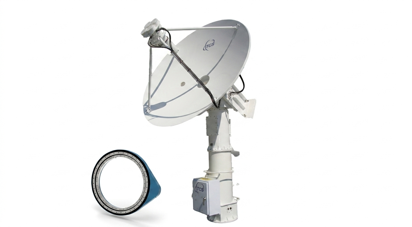
• Azimuth and Elevation Adjustment via Spur Gear Slew Drive – The most basic function is pointing the antenna in a desired direction. Azimuth (horizontal rotation) is typically handled by a large-diameter spur gear slew drive mounted at the base of the antenna. Elevation (vertical tilt) may use a smaller spur gear drive or an alternative linear actuator. Together, these allow full hemispherical coverage.
• Precise Positioning and Holding Torque – Spur gear slew drives with low backlash (measured in arcminutes or even arcseconds) enable highly accurate positioning. For example, a Ku-band VSAT antenna may require pointing accuracy better than 0.2° to maintain link quality. Holding torque – the ability to resist external forces such as wind without backdriving – is achieved by adding a holding brake to the motor or using the natural detent torque of the drive train.
• Dynamic Tracking and Stabilization – For antennas that must follow moving targets (low-earth-orbit satellites, aircraft, drones, or ships), dynamic tracking is essential. Spur gear slew drives excel here because of their low inertia, high stiffness, and rapid response. When combined with a servo control system and position feedback (encoders or resolvers), they can maintain continuous pointing accuracy within fractions of a degree.
Key Advantages of Spur Gear Slew Drive for Antenna Systems
Comparison Between Spur Gear and Worm Gear Slew Drives
| Feature | Spur Gear Slew Drive | Worm Gear Slew Drive |
|---|---|---|
| Transmission efficiency | 85–98% | 40–70% |
| Backlash | Low (precision grades available) | Moderate to high (increases with wear) |
| Self-locking capability | No (brake required) | Yes (in most designs) |
| Output speed | Can support higher speeds | Limited to low speeds |
| Heat generation | Low | High under continuous operation |
| Maintenance | Simple (regular lubrication) | More frequent due to sliding friction |
| Cost | Moderate | Lower for basic designs, higher for precision |
| Suitability for dynamic tracking | Excellent | Poor to fair |
Specific Advantages of Spur Gear Slew Drive for Antenna Systems
• High efficiency – Reduces power consumption and heat dissipation, which is critical for solar-powered or battery-operated remote antenna sites.
• Low backlash – Enables precise pointing and smooth tracking without step-like motion.
• Continuous 360° rotation – Allows uninterrupted azimuth rotation without the rotation limit inherent in some worm gear arrangements.
• Better dynamic response – Makes spur gear drives ideal for tracking low-earth-orbit satellites or fast-moving targets.
• Longer lifespan – Under frequent start-stop operation, reduces total cost of ownership.
Why Spur Gear Slew Drive Is Preferred in Many Antenna Applications
Antenna systems prioritize accuracy, speed, and reliability over self-locking capability. Since most antenna installations include separate holding brakes or motor brakes, the absence of inherent self-locking in spur gear drives is not a disadvantage. Modern control systems easily compensate for any backdriving tendency. Overall, the lower life-cycle cost – despite a potentially higher initial investment – makes spur gear slew drives the preferred choice for performance-oriented antenna applications.
How to Select the Right Spur Gear Slew Drive for Your Antenna?
• Determining Antenna Load and Torque Requirements – Calculate the total weight of the rotating structure (reflector, feed, mounts). Determine the maximum wind load at the installation site, considering both steady wind and gusts. Include ice load if applicable. Then compute the required torque: starting torque (overcoming static friction and inertia), running torque, and holding torque. Always apply a safety factor of at least 1.5 to 2.0.
• Selecting Accuracy Class (Angular Error) – Accuracy is specified as backlash (arcminutes or arcseconds) and positioning repeatability. For general-purpose antennas, 10–30 arcminutes may suffice. For satellite tracking, 1–5 arcminutes is typical. For high-precision radar or TT&C, requirements can fall below 1 arcminute. Spur gear slew drives can be manufactured to precision grades P0, P6, P5, P4, and even P2 for demanding applications.
• Evaluating Environmental Conditions (Wind, Temperature, Corrosion) – Consider maximum and minimum operating temperatures, which affect lubricant viscosity and seal flexibility. In coastal or offshore installations, specify corrosion-resistant materials (zinc-rich primer, epoxy coating, or stainless steel). For dusty environments (desert or construction sites), choose higher IP ratings and heavy-duty seals.
• Choosing the Drive Type (Manual, Electric, Hydraulic) – Manual drives with hand cranks are suitable for infrequent adjustments. Electric drives with AC or DC motors offer remote control and automation; DC motors are common for solar-powered sites. Hydraulic drives provide very high torque density and are used in very large radar antennas or shipboard systems where hydraulic power is already available.
Installation and Integration of Spur Gear Slew Drive
• Interface Matching with Antenna Base – The mounting flange of the slew drive must match the bolt pattern of the antenna pedestal. Ensure concentricity and flatness within specified tolerances to prevent binding or uneven wear. Use hardened washers and torque bolts to factory specifications.
• Connecting Drive and Control Systems – The motor or hydraulic motor must be aligned with the drive pinion shaft. Flexible couplings can accommodate minor misalignment. Position feedback devices (encoders, potentiometers, or resolvers) should be mounted directly on the rotating ring gear or on the pinion shaft for best accuracy. Connect the control system (PLC, motion controller, or antenna controller unit) with proper shielding against electromagnetic interference.
• Sealing and Anti-Corrosion Measures – Inspect all seals before installation. Apply anti-seize compound on mounting bolts. For outdoor antennas, use a breather valve to equalize internal pressure without drawing in moisture. Periodic inspection of seal condition is recommended every six to twelve months.
Applications of Spur Gear Slew Drive in Antenna Systems
• Satellite Communication (SATCOM) Ground Stations – From small VSAT terminals (1.2-meter dishes) to large gateway antennas (9-meter or more), spur gear slew drives provide the azimuth rotation needed to acquire and track geostationary or low-earth-orbit satellites. Their low backlash ensures stable signal strength even in windy conditions.
• Radar Antenna Systems – Surveillance radars require continuous 360° scanning at constant speed. Tracking radars must follow fast-moving targets such as aircraft or missiles. Spur gear slew drives handle both requirements efficiently, with high stiffness and minimal speed fluctuation.
• Telemetry and Tracking Antennas – TT&C antennas communicate with satellites, launch vehicles, and space probes. These antennas demand extremely high pointing accuracy and smooth tracking. Spur gear slew drives with precision grades P4 or P2 are commonly specified.
Maintenance and Troubleshooting for Spur Gear Slew Drive
• Regular Lubrication and Wear Inspection – Use the grease or oil type recommended by the manufacturer. Relubrication intervals depend on duty cycle: every 3–6 months for frequent operation, annually for intermittent use. Inspect gear teeth for pitting, scoring, or abnormal wear via inspection ports or by removing covers.
• Gear Backlash Adjustment – Most spur gear slew drives provide an eccentric shaft or adjustable pinion mount to set or reduce backlash. Perform adjustment when the antenna is powered off and secured. After adjustment, verify smooth rotation and re-check backlash with a dial indicator.
• Common Failures and Corrective Actions – Refer to the table below for typical issues and solutions:
| Failure | Possible Cause | Corrective Action |
|---|---|---|
| Excessive backlash | Wear or improper adjustment | Adjust pinion; replace worn gears |
| Overheating | Lack of lubrication or overload | Relubricate; check load |
| Unusual noise | Contamination or damaged teeth | Clean; inspect; replace if necessary |
| Seal leakage | Aging or damage | Replace seal; check shaft surface |
| Motor stalling | Torque insufficient or binding | Recalculate torque; check alignment |
LyraDrive: Custom Spur Gear Slew Drive Manufacturer for Antenna Systems
Customization Capabilities for Spur Gear Slew Drives
LyraDrive is a professional slew drive supplier specializing in designing and delivering high-quality, customizable, and competitively priced slew drives – with particular expertise in spur gear slew drives for antenna systems. Unlike manufacturers that only offer standard off-the-shelf models, LyraDrive delivers full-scope customized solutions to match your unique application requirements.
For spur gear slew drives used in antenna systems, LyraDrive supports personalized customization across all core parameters, including:
• Dimensions – from 100 mm to 5000 mm outer diameter
• Output torque – matched to your antenna load and wind conditions
• Gear ratio – optimized for speed and resolution
• Mounting flange – custom bolt patterns to fit existing pedestals
• Input shaft – any length, keyway, or spline configuration
• Housing structure – open, enclosed, or lightweight designs
• Material – carbon steel, stainless steel, or specialized alloys
• Sealing grade and protection level – IP54 up to IP67, plus corrosion-resistant coatings for marine antennas
• Motor integration – ready for NEMA, IEC, or servo motors, with or without integrated brakes
Precision Grades and Application-Specific Designs
LyraDrive offers spur gear slew drives with precision grades reaching P0, P6, P5, P4, and even P2 for high-precision antenna applications such as TT&C or phased-array radar. Whether you need drives for heavy-load large antennas, high-speed dynamic tracking systems, corrosion-resistant marine environments, dust-proof desert installations, or clean-room medical-grade antenna systems, LyraDrive tailors every detail to deliver stable, reliable, and long-lasting performance.
With a comprehensive product portfolio that includes worm slew drives, spur gear slew drives, and worm gear drives, LyraDrive serves a wide range of steering, turning, and swiveling applications. However, for antenna systems requiring high efficiency, low backlash, and dynamic tracking capability, the spur gear slew drive remains the optimal choice – and LyraDrive is the partner that delivers it exactly as you need.
How to Get Your Custom Spur Gear Slew Drive?
Just submit your requirement via email, and LyraDrive will provide a complete design with 3D files for your review. From concept to production, the team ensures every spur gear slew drive meets the demanding performance standards of modern antenna systems.